background image

 Technosoft 2021 

13 

iPOS360x HX-CAN Technical Reference


3.4  Connectors and Pinouts 

3.4.1  Pinouts for iPOS360x HX-CAN (differential encoder version; P028.00x.E501) 


Содержание iPOS3602 HX-CAN

Страница 1: ...iPOS3602 HX CAN iPOS3604 HX CAN Intelligent Servo Drive for Step DC Brushless DC and AC Motors Intelligent Servo Drives Technical Reference Technosoft 2021 P091 028 iPOS360X HX CAN UM 0621 ...

Страница 2: ...OS360x HX CAN single ended encoder version P028 00x E561 14 3 4 3 Pinouts for iPOS360x HX CAN linear halls encoder version P028 00x E571 15 3 4 4 Mating Connectors 16 3 4 5 Cable Set 16 3 5 Connection diagrams 17 3 5 1 iPOS360X HX CAN connection diagram differential encoder version P028 00x E501 17 3 5 2 iPOS360X HX CAN connection diagram single ended encoder version P028 00x E561 18 3 5 3 iPOS360...

Страница 3: ...5 10 2 Recommendation for wiring 31 3 5 11 CAN bus connection 32 3 5 11 1 CAN connection 32 3 5 11 2 Recommendation for wiring 32 3 5 12 Disable of Autorun Mode 33 3 6 CAN Operation Mode and Axis ID Selection 33 3 6 1 Selection of the Operation Mode 33 3 6 2 Selection of the Axis ID 34 3 6 3 LED indicators 34 3 7 Electrical Specifications 35 3 7 1 Operating Conditions 35 3 7 2 Storage Conditions 3...

Страница 4: ...x drives you need to pass through 3 steps Step 1 Hardware installation Step 2 Drive setup using Technosoft EasySetUp software for drive commissioning Step 3 Motion programming using one of the options A CANopen master1 The drives built in motion controller executing a Technosoft Motion Language TML program developed using Technosoft EasyMotion Studio software A TML_LIB motion library for PCs Windo...

Страница 5: ... v4 1 device profile for drives and motion control now included in IEC 61800 7 1 Annex A IEC 61800 7 201 and IEC 61800 7 301 standards Motion Programming using EasyMotion Studio part no P091 034 ESM UM xxxx describes how to use the EasyMotion Studio to create motion programs using in Technosoft Motion Language TML EasyMotion Studio platform includes EasySetUp for the drive motor setup and a Motion...

Страница 6: ...on and setup It is imperative to implement the safety instructions listed hereunder This information is intended to protect you the drive and the accompanying equipment during the product operation Incorrect handling of the drive can lead to personal injury or material damage The following safety symbols are used in this manual WARNING SIGNALS A DANGER TO THE OPERATOR WHICH MIGHT CAUSE BODILY INJU...

Страница 7: ...arding Article 33 of the European REACH Regulation 1907 2006 Registration Evaluation Authorization and Restriction of Chemicals which came into force on 01 06 2007 RoHS Compliance Technosoft SA here with declares that this product is manufactured in compliance with the RoHS directive 2002 95 EC on the restriction of the use of certain hazardous substances in electrical and electronic equipment RoH...

Страница 8: ...he master and the drives in complex multi axis applications reducing both the development time and the overall communication requirements For example instead of trying to command each movement of an axis you can program the drives using TML to execute complex motion tasks and inform the master when these tasks are done Thus for each axis control the master job may be reduced at calling TML functio...

Страница 9: ...itable for the control of rotary or linear brushless DC brush and step motors Very compact design Sinusoidal FOC or trapezoidal Hall based control of brushless motors Open or closed loop control of 2 and 3 phase steppers Various modes of operation including torque speed or position control position or speed profiles Cyclic Synchronous Position CSP for CANopen mode external reference mode analogue ...

Страница 10: ... Over voltage Under voltage Over current Communication error Control error Over temperature Firmware on drive F508M or F523E for iPSO3604 F509M or F524E for iPSO3602 2 3 Identification Labels Figure 2 3 1 iPOS360X HX CAN identification labels The iPOS360X HX can has the following part number and name on the identification label Product Name Part Number Firmware Description iPOS3602 HX CAN P028 001...

Страница 11: ... Yes Yes Yes Incr encoder Digital Hall Yes Yes Sin Cos encoder Yes Digital halls only Yes Linear Halls Yes Tacho Yes Open loop no sensor Yes Yes Open loop with step loss detection using incr Encoder Yes Yes Open loop with incr encoder on load Yes Yes Linear Halls are supported with a different part number 3 Hardware Installation 3 1 iPOS360X HX CAN Board Dimensions Figure 3 1 1 iPOS360X HX CAN dri...

Страница 12: ...s If ventilation driven by natural convection is not enough to maintain the temperature surrounding the iPOS360x HX CAN drive s then alternate forced cooling methods must be applied Remark In case of using a metallic box with ventilation openings all spacing values may be reduced substantially With proper ventilation keeping the air surrounding the iPOS360x HX CAN inside the limits indicated the s...

Страница 13: ... Technosoft 2021 13 iPOS360x HX CAN Technical Reference 3 4 Connectors and Pinouts 3 4 1 Pinouts for iPOS360x HX CAN differential encoder version P028 00x E501 ...

Страница 14: ... Technosoft 2021 14 iPOS360x HX CAN Technical Reference 3 4 2 Pinouts for iPOS360x HX CAN single ended encoder version P028 00x E561 ...

Страница 15: ... Technosoft 2021 15 iPOS360x HX CAN Technical Reference 3 4 3 Pinouts for iPOS360x HX CAN linear halls encoder version P028 00x E571 ...

Страница 16: ... Ordering information Part No Description Package components Connectors P028 040 C099 CCS iPOS360x BXD Complete cable set 100 cm with differential encoder cable 1 x Motor Hall cable J2 1 x Supply cable J1 2 x CAN cable RS232 cable J5 J6 J7 1 x I O cable J4 1 x Differential Encoder cable J3 P028 040 C098 CCS iPOS360x BXE Complete cable set 100 cm with single ended encoder cable 1 x Motor Hall cable...

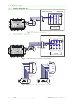
Страница 17: ...nection diagrams 3 5 1 iPOS360X HX CAN connection diagram differential encoder version P028 00x E501 Figure 3 5 1 iPOS360X HX CAN Connection diagram with a differential encoder For other available feedback motor options check the detailed connection diagrams below ...

Страница 18: ...ence 3 5 2 iPOS360X HX CAN connection diagram single ended encoder version P028 00x E561 Figure 3 5 2 iPOS360X HX CAN Connection diagram with a single ended encoder For other available feedback motor options check the detailed connection diagrams below ...

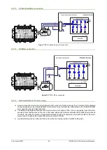
Страница 19: ...ence 3 5 3 iPOS360X HX CAN connection diagram linear halls encoder version P028 00x E571 Figure 3 5 3 iPOS360X HX CAN Connection diagram with a linear halls encoder For other available feedback motor options check the detailed connection diagrams below ...

Страница 20: ...by software 3 When sets as PNP the inputs are compatible with PNP type outputs input must receive a positive voltage value 5 36V to change its default state 3 5 4 2 NPN inputs Figure 3 5 4 2 24V Digital NPN Inputs connection Remarks 1 If Vlog is not supplied the digital inputs will not work 2 The inputs are selectable as PNP NPN by software 3 When sets as NPN the inputs are compatible with NPN typ...

Страница 21: ...s are NOT compatible with PNP inputs Even if it seems to work proper operation is NOT guaranteed 3 5 5 5V Digital I O Connection Figure 3 5 5 1 5V Digital I O connection Remarks 1 The inputs are selectable as PNP NPN by software For this connection they are selected as NPN 2 The inputs are compatible with TTL 5V LVTTL 3 3V CMOS and open collector outputs 3 The outputs are compatible with TTL 5V in...

Страница 22: ...is single ended use a 2 wire twisted shielded cable as follows 1st wire connects the live signal to the drive input 2nd wire connects the source ground to the drive ground shield will be connected to the drive ground terminal b If the analogue signal source is differential and the signal source ground is isolated from the drive GND use a 2 wire twisted shielded cable as follows 1st wire connects t...

Страница 23: ... Motor connections 3 5 7 1 Brushless Motor connection Figure 3 5 7 1 Brushless motor connection 3 5 7 2 2 phase Step Motor connection Figure 3 5 7 2 2 phase step motor connection one coil per phase Figure 3 5 7 3 2 phase step motor connection two coils per phase ...

Страница 24: ...ed cable for the motor wires Connect the cable shield to the iPOS360X GND pin Leave the other end disconnected b The parasitic capacitance between the motor wires must not bypass 10nF If very long cables tens of meters are used this condition may not be met In this case add series inductors between the iPOS360X outputs and the cable The inductors must be magnetically shielded toroidal for example ...

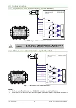
Страница 25: ...ONNECT UNTERMINATED WIRES THEY MIGHT PICK UP UNWANTED NOISE AND GIVE FALSE ENCODER READINGS 3 5 8 2 Differential Incremental Encoder Connection only with P028 00x E501 Figure 3 5 8 2 Differential incremental encoder connection Remarks 1 For the encoder differential connection 120Ω 0 25W terminators are included in the drive 2 The length of the cables must be up to 30m reducing the exposure to volt...

Страница 26: ... environment 3 5 8 4 Digital Hall Connection for direct motor control without an encoder only with P028 00x E561 Figure 3 5 8 4 Digital Hall connection Remarks 1 This connection is required when using only Digital hall signals as the main feedback device for motor control In this case no incremental encoder is needed 2 Do not connect unterminated wires They might pick up unwanted noise and give fa...

Страница 27: ...th A Sin B Cos with B Cos Z with Z Use another twisted pair for the 5V supply and GND b Always use shielded cables to avoid capacitive coupled noise when using single ended encoders or Hall sensors with cable lengths over 1 meter Connect the cable shield to the GND at only one end This point could be either the iPOS360x using the GND pin or the encoder motor Do not connect the shield at both ends ...

Страница 28: ... add a capacitor of at least 2 200μF rated at an appropriate voltage right on the terminals of the iPOS3604 respectively 1 000μF for the iPOS3602 3 5 9 3 Recommendations to limit over voltage during energy regeneration During abrupt motion decelerations or reversals the regenerative energy is injected into the motor power supply This may cause an increase of the motor supply voltage depending on t...

Страница 29: ...he drive is used with a step motor The chopping resistor option can be found in the Drive Setup dialogue within EasyMotion EasySetup The chopping will occur when DC bus voltage increases over UCHOP This parameter UCHOP should be adjusted depending on the nominal motor supply Optimally from a braking point of view UCHOP should be a few volts above the maximum nominal supply voltage This setting wil...

Страница 30: ...a peak power CR MAX PEAK R U P 2 Remarks 1 If CR CHOP PEAK MAX P U I U 2 2 the braking power PCR must be reduced by increasing either td the time to decelerate or C the external capacitor on the motor supply 2 If CR CHOP NOM CYCLE d CR P U I t t P 2 2 2 either the braking power must be reduced see Remark 1 or tCYCLE the time interval between braking cycles must be increased WARNING THE CHOPPING RE...

Страница 31: ...hielded cable with shield connected to BOTH ends Do not use the shield as GND The ground wire must be included inside the shield like the 232Rx and 232Tx signals b Always power off all the iPOS360X supplies before inserting removing the RS 232 serial connector c Do not rely on an earthed PC to provide the iPOS360X GND connection The drive must be earthed through a separate circuit Most communicati...

Страница 32: ...ted together with CAN Lo It is recommended but not mandatory to use a shielded cable If so connect the shield to GND The cable impedance must be 105 135 ohms 120 ohms typical and a capacitance below 30pF meter b Whenever possible use daisy chain links between the CAN nodes Avoid using stubs A stub is a T connection where a derivation is taken from the main bus When stubs can t be avoided keep them...

Страница 33: ...nnecting all digital Hall inputs to GND as shown in Figure 3 23 This option is particularly useful when you are unable to establish communication with the drive b temporarily connect JP1 in position 1 2 to switch to CANopen protocol After a drive restart the drive will not auto run any program while in CANopen Reconfigure the settings as needed and switch back to TMLCAN After the drive is set in s...

Страница 34: ...osition AxisID 0x0 255 0x1 1 0x2 2 0x3 3 0x4 4 0x5 5 0x6 6 0x7 7 0x8 8 0x9 9 0xA 10 0xB 11 0xC 12 0xD 13 0xE 14 0xF 15 3 6 3 LED indicators Figure 3 6 3 1 LED indicators Table 3 6 3 LED indicators LED no LED name LED color Function 1 Drive Ready green Lit after power on when the drive initialization ends Turned off when an error occurs 2 Drive Error red Turned on when the drive detects an error co...

Страница 35: ...een drives and nearby walls 30 mm Between drives and roof top 20 mm Spacing required for horizontal mounting Between adjacent drives 4 mm Between drives and nearby walls 5 mm Space needed for drive removal 10 mm Between drives and roof top 15 mm Insertion force Using recommended mating connectors without retainer 20 36 N Extraction force 5 10 N 3 7 4 Environmental Characteristics Min Typ Max Units...

Страница 36: ...alue for ripple 5 of measurement range VMOT 36 V FPWM 20 kHz 250 µH FPWM 40 kHz 120 FPWM 80 kHz 60 FPWM 60 kHz 100 FPWM 100 kHz 45 Absolute minimum value limited by short circuit protection VMOT 36 V FPWM 20 kHz 75 µH FPWM 40 kHz 25 FPWM 60 kHz 20 FPWM 80 kHz 10 FPWM 100 kHz 5 Motor electrical time constant L R Recommended value for 5 current measurement error due to ripple FPWM 20 kHz 250 µs FPWM...

Страница 37: ... leakage current external load to VLOG VOUT VLOG max 40V 0 1 0 2 mA Minimum pulse width 2 µs ESD protection Human body model 5 kV 3 7 10 Digital Hall Inputs Hall1 Hall2 Hall3 Min Typ Max Units Mode compliance TTL CMOS Open collector Default state Input floating wiring disconnected Logic HIGH Input voltage Logic LOW 0 0 8 V Logic HIGH 2 5 Floating voltage not connected 4 4 Absolute maximum surge du...

Страница 38: ... Differential mode compliance TIA EIA 422 A Input voltage differential Hysteresis 0 06 0 1 0 2 V Operating range 14 14 Input voltage common mode Operating range A to GND etc 11 14 Input impedance A B Z 120 Ω A B Z 1 3 1 6 kΩ Differential mode 0 10 MHz Differential mode 50 ns ESD protection Human body model 1 kV 3 7 15 Single ended encoder inputs A B Z for PN P028 00x E561 Min Typ Max Units Single ...

Страница 39: ...8 Supply Output 5V Min Typ Max Units 5V output voltage Current sourced 350mA 4 8 5 5 2 V 5V output current iPOS360X HX CAN 250 500 540 mA Short circuit protection Yes Drive resets at event Over voltage protection NOT protected ESD protection Human body model 1 kV 3 7 19 Conformity EU Declaration 2014 30 EU EMC 2014 35 EU LVD 2011 65 EU RoHS 1907 2006 EC REACH 93 68 EEC CE Marking Directive EC 428 ...

Страница 40: ... phase 24V 20KHz 4 phase 24V 0 0 5 1 1 5 2 2 5 0 1 2 3 4 5 6 7 8 9 10 Current A Altitude Km Altitude De rating 0 0 2 0 4 0 6 0 8 1 1 2 1 4 1 6 1 8 2 2 2 2 4 0 10 20 30 40 50 60 70 80 90 100 Current A PWM Frequency KHz PWM Frequency De rating 36V 3 phase 24V 4 phase 36V 4 phase 0 10 20 30 40 50 60 70 0 0 5 1 1 5 2 2 5 3 3 5 Time s Current A Overcurrent Diagram INOM 2 A IMAX 3 2 A I2T 250 A2s tPK 24...

Страница 41: ...ime The E2ROM is mapped in the address range 4000h to 4FFFh It is used to keep in a non volatile memory the TML programs the cam tables and the drive setup information Remark EasyMotion Studio handles automatically the memory allocation for each motion application The memory map can be accessed and modified from the main folder of each application Figure 4 1 iPOS360X HX Memory Map TML Programs 400...

Отзывы: