TECHNICAL DATA& SERVICE MANUAL
INDOOR UNIT:
CA8FIA0R5IAA
0.8180.592.01 10/2012
38.7106.020
SPLIT SYSTEM AIR CONDITIONER
Model No.
Product Code No.
Страница 1: ...TECHNICAL DATA SERVICE MANUAL INDOOR UNIT CA8FIA0R5IAA 0 8180 592 01 10 2012 38 7106 020 SPLIT SYSTEM AIR CONDITIONER Model No Product Code No CA8FIA0R5IAA ...
Страница 2: ...ow wiring to touch the refrigerant tubing compressor or any moving parts of the fan Do not use multi core cable when wiring the power supply and control lines Use separate cables for each type of line When transporting Be careful when picking up and moving the indoor and outdoor units Get a partner to help and bend your knees when lifting to reduce strain on your back Sharp edges or thin aluminium...
Страница 3: ...Leds off function 16 4 17 Capacity Test Mode 16 4 18 Diagnostic 17 4 19 Indoor unit jumpers Configuration 18 4 20 Outdoor unit jumpers Configuration 18 5 INDOOR UNIT AND REMOTE CONTROL ADDRESS 19 5 1 Address Switches only for multisplit 19 5 2 Refrigerant Circuit Check only for multisplit 19 5 3 Changing the Address of the Air Conditioner 19 6 TROUBLESHOOTING 20 6 1 Check before and after troubles...
Страница 4: ...mensions Unit Height mm Width mm Depth mm Ceiling panel Height mm Width mm Depth mm Package dimensions Unit Height mm Width mm Depth mm Volume m3 Ceiling panel Height mm Width mm Depth mm Volume m3 Weight Unit Net kg Shipping kg Ceiling panel Net kg Shipping kg DATA SUBJECT TO CHANGE WITHOUT NOTICE 650 220 240 V 50 Hz 230 V 730 730 380 744 6 35 1 4 575 575 64 Microprocessor I C thermostat Wireless...
Страница 5: ...s Type Operating temp Open C Close Run capacitor µF VAC Flap Motor Type Model Rating Coil resistance Ambient temp 25 C Heat Exch Coil Coil Rows Fin pitch mm face area m2 DATA SUBJECT TO CHANGE WITHOUT NOTICE WHT RED 101 GRY RED 29 BLK GRY 63 2 Internal thermal protector 130 10 Automatic 0 258 SAC DCI IDU 4 950 790 700 Aluminium plate fin Copper tube 1 1 3 440 0 31 0 28 0 25 BRN WHT 19 Microprocess...
Страница 6: ...Coil sensor Resistance k Thermistor Room sensor Resistance k Drain pump Model Rating Voltage Input Total head capacity Safety float switch Model Contact rating 0 4 l min P200AC 001 230 Vac 0 4 A PC 309564003 220 240 V 50 Hz 14 W Primary Secondary 0028TRA008 AC 230 V 50 Hz 13 V 6VA 120 C NTC THERMISTOR 10 at 25 C 10 at 25 C NTC THERMISTOR 6 ...
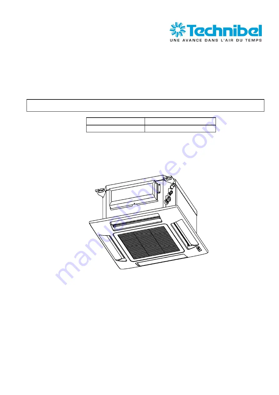
Страница 7: ...2 DIMENSIONAL DATA CA8FIA0R5IAA Unit mm 7 ...
Страница 8: ...3 ELECTRICAL DATA 3 1 Electric Wiring Diagrams 8 ...
Страница 9: ...ns but in any case The minimum time interval between an OFF and a ON operation is not lower than 3 minutes The minimum operating time is not lower than 3 minutes The maximum acceleration deceleration rate is fixed at 20rpm sec During the start up compressor speed increases according to a defined rule which is independent from the thermal load calculation 4 1 2 Multisplit available modes If the uni...
Страница 10: ...n The minimum off time of compressor is 3 minutes The indoor fan can change speed only after it has operated at the same speed for 30 sec if in AUTO and 1 sec for the other settings High Med Low 4 3 Heat Mode Operation The Heating mode operation is similar to the Cooling mode operation The CM FMO and FMI are controlled by the same parameters The FMI will not be turned on until the indoor coil temp...
Страница 11: ... two modes is according to the above graph and following table If 3 C Dt 1 C and the compressor is off for more than 1 hour If Dt 3 C and compressor is off for more than 3 minutes If 1 C Dt 3 C and the compressor is off for more than 1 hour If Dt 3 C and compressor is off for more than 3 minutes Dt RAT SPT Refer to the sections 4 1 COOLING MODE and 4 2 HEATING MODE for system operation details COO...
Страница 12: ...T 1 C LEVEL 2 FMO switches 9 minutes off and 3 minutes ON 15 C FMI switches between L and LL every 30 seconds RV off CM off 15 C DRY OFF ZONE FMO off FMI off RV off SPT Set Point Temperature 4 6 Fan Mode Operation With this mode the indoor fan is turned on while CM FMO and RV stay off all the time The user can select between 3 speeds HIGH MEDIUM and LOW 4 7 Auto Fan speed With this option selected...
Страница 13: ... coil temperature ICT decreases and acts by decreasing the compresor speed The system exit this protection routine when ICT temperature rises above 5 C 4 9 2 Cold draft This feature prevents the supply of cold air forcing the indoor fan to a speed which cannot be changed by the user If the ICT temperature goes down 32 C in descending or does not reach 37 C in rising the speed fan is set as shown b...
Страница 14: ...a built in thermistor is always monitored by the control system and kept operating in a safe area If temperature exceeds 100 C operation is automatically stopped 4 10 4 Outdoor fan power module overheating The module temperature detected by a built in thermistor is always monitored by the control system and kept operating in a safe area If temperature exceeds 100 C operation is automatically stopp...
Страница 15: ...emote controller icon I FEEL shown on the display This feature provides a personalised environment since the temperature can be detected where the remote controller is located It is possible to de activate this option pressing the I FEEL button on the remote controller In this case the I FEEL icon is no longer displayed and room temperature is detected through the sensor included in the indoor uni...
Страница 16: ... for more than 5 seconds the IFEEL and FAN buttons on the remote controller With this option active the OPERATION TIMER and STANDBY lamps are switched off even during operation they activates only in case of diagnostic signaling 4 17 Capacity Test mode This is a special operating mode used when testing the performance of the A C In this case the main components of the A C compressor outdoor fan in...
Страница 17: ...f more than one trouble present is always showed at first the one with the highest priority 1 2 3 etc Sensor damaged means a situation where sensor is short circuited or opened In case of damaged sensors the system CM FMO FMI etc if in OFF state does not start Effects LD2 opr LD3 timer LD1 stby 4 RAT probe damaged F O F 3 ICT probe damaged F F O 2 communication error F F F 1 fault on outdoor unit ...
Страница 18: ... is shipped with jumpers set according to the following table JUMPER STATUS JP1 open JP2 open 4 20 Outdoor Unit Jumpers Configuration Unit is shipped with jumpers set according to the following table JUMPER STATUS JP1 open JP2 closed JP3 open 18 ...
Страница 19: ...remote control unit directly at the air conditioner receiver System starts and runs for 3 minutes After 3 minutes operation in case the setting is right the unit switches to COOL mode and stops set point 32 C the system is ready to operate in case the setting is wrong the STANDBY lamp flashes check the setting of indoor units and the connections of the refrigerant circuits 5 3 Changing the Address...
Страница 20: ...wer is being supplied WARNING If the following troubleshooting must be done with power supplied be careful not to touch any uninsulated live part that can cause electric shock 6 2 CIRCUIT BREAKER TRIPS OR FUSE BLOWS When circuit breaker is set to ON it trips in a few moments Resetting is not possible Measure insulation resistance There is a possibility of ground fault If resistance value is 1 Mohm...
Страница 21: ...de YES Is the unit in protection mode see par 4 9 e 4 10 Wait some minutes to restore normal condition YES NO CASE 1 CASE 2 There is a fault signaling Check outdoor unit leds signaling see par 4 18 Normal leds configuration 2 IN INDOOR UNIT THERE IS ONE LED ON AT LEAST AND THE UNIT RECEIVES THE REMOTE CONTROL SIGNAL NO see section 6 4 see section 6 6 21 ...
Страница 22: ...the sensor COMMUNICATION ERROR Is the communication fuse blown Replace fuse 100mA The fuse may be not fitted rightly in the fuseholder Check for right connection of communication wires Check outdoor unit Is there any led on See section 6 5 Turn off power supply and after 3 minutes turn on again Outdoor unit PCB assy is defective NO YES YES NO See section 6 6 FAULT ON THE OUTDOOR UNIT Replace outdd...
Страница 23: ...6 4 OUTDOOR UNIT DOES NOT RUN AND NO FAULT IS DISPLAYED 6 5 ONLY OUTDOOR UNIT IS OFF 23 ...
Страница 24: ...The fuse may be not fitted rightly in the fuseholder Check for right connection of communication wires Turn off power supply and after 3 minutes turn on again NO See section 6 3 FAULT ON THE INDOOR UNIT YES COMPRESSOR FAN OVERCURRENT OVERTEMPERATURE Replace the compressor fan YES Measure the resistance of compressor fan motor windings Is it defective Replace outdoor unit PCB NO PFC FAULT Measure t...
Страница 25: ... air filters Check the air filters Are they clogged YES NO Check the expansion valve coil Is it rightly connected and the resistance value correct Replace the expansion valve coil NO There is the possibilty of gas shortage YES Is the remote controller directly under the airflow of the unit NO Change the position of the remote controller YES Is the fan motor set in low speed Set fan speed in medium...
Страница 26: ...IES ARE OBSERVED 2 OPERATION DOES NOT SWITCH FROM HEAT TO COOL AND FROM COOL TO HEAT Remote controller unit may be defective Receiver assy may be defective Check the connection of reversing valve coil Check resistance of reversing valve coil 26 ...
Страница 27: ...6 8 NOISE PROBLEM 27 ...
Страница 28: ...disired electric part from terminal plate PCB assy capacitor etc Similary disconnect the connector Then measure the insulation resistance fig 1 to 4 Refer to electric wiring diagram NOTE If the probe cannot enter the poles because the hole is too narrow then use a probe with a thinner pin 7 2 Checking Continuity of fuse on PCB assy Remove PCB assy from electrical component box fig 5 Then pull out ...
Страница 29: ...0 8180 592 01 10 2012 R D 28 Reyrieux BP 131 01601 Trévoux CEDEX France Tél 04 74 00 92 92 Fax 04 74 00 42 00 R C S Bourg en Bresse B 759 200 728 ...