1
EU-402N PWM
Страница 1: ...1 EU 402N PWM...
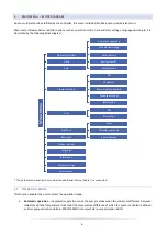
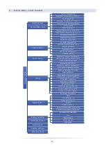
Страница 2: ...8 Display contrast 9 2 9 Language 9 2 10 Information 9 2 11 Factory settings 9 V Service menu 9 3 Service menu block diagram 10 3 1 Schemat instalacji 11 3 2 Accmulation tank 18 3 3 Solar collector 20...
Страница 3: ...f the cables The regulator should not be operated by children NOTE The device may be damaged if struck by a lightning Make sure the plug is disconnected from the power supply during storm Any use othe...
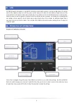
Страница 4: ...oiler may be done directly from the controller An additional signal relay is necessary in order to control the heater The controller offers PWM pump control option enabling the user to adjust its rota...
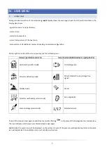
Страница 5: ...Icon of active additional device peripherals Automatic operation mode Circulating pump Collector defrosting mode Pellet CH boiler fire up voltage free signal Holiday mode Heater Collector overheating...
Страница 6: ...mode Automatic operation In automatic operation mode the pump is active when the minimum difference between collector and tank temperature is reached the temperature difference at which the pump is en...
Страница 7: ...mp is disabled when the temperature drops by 5 C Collector temperature is lower than the tank temperature the pump is activated in order to cool the tank down It remains active until the temperatures...
Страница 8: ...de must be generated Internet module parameters such as IP address IP mask gate address etc may be set manually or by selecting DHCP option 2 5 GSM MODULE GSM Module is an optional device which cooper...
Страница 9: ...ness changes after a few seconds of inactivity 2 8 DISPLAY CONTRAST This parameter is used to adjust the display contrast 2 9 LANGUAGE This option is used to select the language version of the control...
Страница 10: ...imum receiver temperature Receiver activation temperature Heat receiver hysteresis Pumps Regulated revolutions Maximum collector temperature Solar pump deactivation delta Solar pump activation delta G...
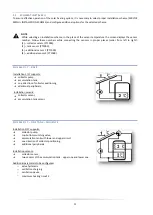
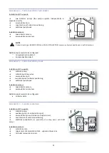
Страница 11: ...ditional sensor 1 PT1000 4 additional sensor 2 PT1000 SCHEME 1 17 BASIC Installation 1 17 supports collector pump accumulation tank one direction of collector positioning additional peripherals Instal...
Страница 12: ...SCHEME 4 17 TWO COLLECTORS VALVE Installation 4 17 supports collector pump collector switching valve accumulation tank two directions of collector positioning additional peripherals Installation senso...
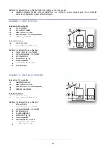
Страница 13: ...parameters to be configured pre set temperature of tank 2 maximum temperature of tank 2 tank 2 hysteresis oscillation charging oscillation pause maximum heating time Z2 valve hysteresis SCHEME 7 17 TW...
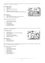
Страница 14: ...2 Pump activation delta 2 SCHEME 9 17 HEAT EXCHANGER Installation 9 17 supports collector pump valve switching between the tank and heat exchanger accumulation tank heat exchanger heat receiver one d...
Страница 15: ...HEATING Installation 11 17 supports collector pump valve switching between direct boiler circulation and through tank circulation or pump accumulation tank with lower and upper circuit CH boiler retu...
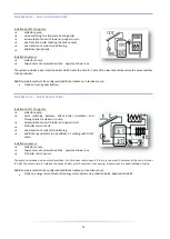
Страница 16: ...ivation delta 2 Heat receiver maximum receiver temperature heat receiver hysteresis SCHEME 13 17 TWO COLLECTORS PUMP VALVE TANK AND ADDITIONAL TANK CONNECTED IN SERIES Installation 13 17 supports coll...
Страница 17: ...ecting an additional device Peripherals submenu is not available in the service menu Switching valve controlling the additional receiver is connected in the place of peripheral device Additional param...
Страница 18: ...ensors of accumulation tank heat receiver sensor Additional parameters to be configured additional submenu in service menu Heat receiver maximum receiver temperature receiver activation temperature he...
Страница 19: ...e to switch again Scheme 2 and 6 the setting concerns valve control when cooling the collector down in summer mode or alarm mode as well as when defrosting The valve hysteresis determines the differen...
Страница 20: ...installation anti freeze temperature was introduced This parameter determines the minimum safe temperature at which glycol liquid does not freeze temperature measured at the collector In case of a sig...
Страница 21: ...or overheat mode Solar pump deactivation delta This function determines the difference between the collector temperature and the tank temperature at which the pump is deactivated so as not to cool dow...
Страница 22: ...ing heating circuit 1 is given absolute priority and switching to circuit 2 heating is possible only after the pre set temperature of circuit 1 is reached In the case of scheme 2 the first circulation...
Страница 23: ...selected the user should adjust operation time and pause time of the pump during its activity Next the user should define the hours of pump operation using From hour and Through hour functions Enteri...
Страница 24: ...ch the controller activates the heater Next the user selects the time period in which the electric heating function will be active using from hour and through hour parameters Contact in compatible wit...
Страница 25: ...glycol concentration in water given in percent Calibration this function allows the user to calibrate the temperature difference between the sensors The temperature is measured in the place where the...
Страница 26: ...for scheme 11 This parameter determines the minimum difference between the tank temperature and the boiler return circulation temperature at which the valve switches to standard boiler circulation wit...
Страница 27: ...see SERVICE MENU Solar Collector Alarm Hysteresis In the case of two tanks both of them are used to cool down the overheated collector at the same time or one by one depending on the operation algori...
Страница 28: ...max output load 1A Pump 2 Valve max output load 1A Additional output 1 max output load 1A Fuse 3 15A IX INSTALLATION The controller should be installed by a qualified electrician Make sure that the pl...
Страница 29: ...torial diagram it cannot replace CH installation project Its aim is to present how the controller may be expanded This heating installation diagram does not include protective elements which are neces...
Страница 30: ...30 PWM pump connection scheme...
Страница 31: ...electromagnetic compatibility EU OJ L 96 of 29 03 2014 p 79 Directive 2009 125 EC establishing a framework for the setting of ecodesign requirements for energy related products as well as the regulati...
Страница 32: ...32...