


TECDrive TEC-3 User Guide Revision 1.20
www.tecmotors.co.uk/tecdrive
21
6
Pa
ra
m
e
ter
s
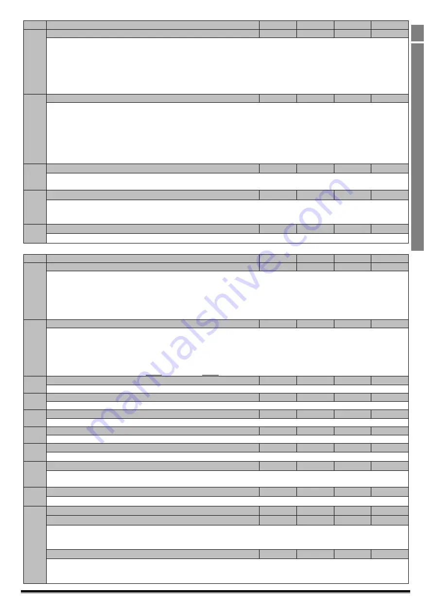
Par.
Description
Minimum
Maximum
Default
Units
P-46
PI Feedback Source Select
0
5
0
-
Selects the source of the feedback signal to be used by the PI controller.
0: Analog Input 2
(Terminal 4) Signal level readable in P00-02.
1 : Analog Input 1
(Terminal 6) Signal level readable in P00-01
2: Motor Current
. Scaled as % of P-08.
3 : DC Bus Voltage
Scaled 0
–
1000 Volts = 0
–
100%
4: Analog 1
–
Analog 2
. The value of Analog Input 2 is subtracted from Analog 1 to give a differential signal. The value is limited to 0.
5: Largest (Analog 1, Analog 2)
. The larger of the two analog input values is always used for PI feedback.
P-47
Analog Input 2 Signal Format
-
-
-
U0-10
= 0 to 10 Volt Signal
= 0 to 20mA Signal
= 4 to 20mA Signal, the TECDrive will trip and show the fault code
if the signal level falls below 3mA
= 4 to 20mA Signal, the TECDrive will run at Preset Speed 1 (P-20) if the signal level falls below 3mA
= 20 to 4mA Signal, the TECDrive will trip and show the fault code
if the signal level falls below 3mA
= 20 to 4mA Signal, the TECDrive will run at Preset Speed 1 (P-20) if the signal level falls below 3mA
= Use for motor thermistor measurement, valid with any setting of P-15 that has Input 3 as E-Trip.
Trip level : 3kΩ, reset 1kΩ
P-48
Standby Mode Timer
0.0
25.0
0.0
s
When standby mode is enabled by setting P-48 > 0.0, the drive will enter standby following a period of operating at minimum speed
(P-02) for the time set in P-48. When in Standby Mode, the drive display shows
, and the output to the motor is disabled.
P-49
PI Control Wake Up Error Level
0.0
100.0
5.0
%
When the drive is operating in PI Control Mode (P-12 = 5 or 6), and Standby Mode is enabled (P-48 > 0.0), P-49 can be used to define
the PI Error Level (E.g. difference between the setpoint and feedback) required before the drive restarts after entering Standby
Mode. This allows the drive to ignore small feedback errors and remain in Standby mode until the feedback drops sufficiently.
P-50
User Output Relay Hysteresis
0.0
100.0
0.0
%
Sets the hysteresis level for P-19 to prevent the output relay chattering when close to the threshold.
6.3.
Advanced Parameters
Par.
Description
Minimum
Maximum
Default
Units
P-51
Motor Control Mode
0
5
0
-
0: Vector speed control mode
1: V/f mode
2: PM motor vector speed control
3: BLDC motor vector speed control
4: Synchronous Reluctance motor vector speed control
5: LSPM motor vector speed control
P-52
Motor Parameter Autotune
0
1
0
-
0 : Disabled
1: Enabled
. When enabled, the drive immediately measures required data from the motor for optimal operation. Ensure all motor
related parameters are correctly set first before enabling this parameter.
This parameter can be used to optimise the performance when P-51 = 0.
Autotune is not required if P-51 = 1.
For settings 2
–
5 of P-51, autotune MUST be carried out AFTER all other required motor settings are entered.
P-53
Vector Mode Gain
0.0
200.0
50.0
%
Single Parameter for Vector speed loop tuning. Affects P & I terms simultaneously. Not active when P-51 = 1.
P-54
Maximum Current Limit
0.0
175.0
150.0
%
Defines the max current limit in vector control modes
P-55
Motor Stator Resistance
0.00
655.35
-
Ω
Motor stator resistance in Ohms. Determined by Autotune, adjustment is not normally required.
P-56
Motor Stator d-axis Inductance (Lsd)
0
6553.5
-
mH
Determined by Autotune, adjustment is not normally required.
P-57
Motor Stator q-axis Inductance (Lsq)
0
6553.5
-
mH
Determined by Autotune, adjustment is not normally required.
P-58
DC Injection Speed
0.0
P-01
0.0
Hz / RPM
Sets the speed at which DC injection current is applied during braking to Stop, allowing DC to be injected before the drive reaches
zero speed if desired.
P-59
DC Injection Current
0.0
100.0
20.0
%
Sets the level of DC injection braking current applied according to the conditions set in P-32 and P-58.
P-60
Motor Overload Management
-
-
-
-
Index 1 : Thermal Overload Retention
0
1
0
1
0 : Disabled
1: Enabled.
When enabled, the drive calculated motor overload protection information is retained after the mains power is removed
from the drive.
Index 2 : Thermal Overload Limit Reaction
0
1
0
1
0: It.trp.
When the overload accumulator reaches the limit, the drive will trip on It.trp to prevent damage to the motor.
1: Current Limit Reduction.
When the overload accumulator reaches 90% of, the output current limit is internally reduced to 100%
of P-08 in order to avoid an It.trp. The current limit will return to the setting in P-54 when the overload accumulator reaches 10%


