P a g e 18 | 64
TM1-5GM2020SG
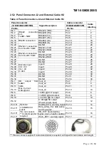
2.5.2 Panel Connector J2 and External Cable H2
Table 4: Panel Connectors J2 and External Cable H2
Panel Connector
Signal Description
Cable connector
Cable
labelling
J2: D38999/24WD35SN
D38999/26WD35PN
Pin No.
Pin No.
Pin 1 RS422 connection
from
TeaM1- 5GM
RS422A (RX+)
Pin 1
1
Pin 2
RS422B (RX-)
Pin 2
2
Pin 4
RS422Z (TX-)
Pin 4
4
Pin 5
RS422Y (TX+)
Pin 5
5
Pin 18 RS485 connection
RS485A (D+)
Pin 18
18
Pin 19
RS485B (D-)
Pin 19
19
Pin 20 RS232-1 connection
from TeaM1- 5GM
DGND
Pin 20
20
Pin 21
RS232-1-TXD
Pin 21
21
Pin 22
RS232-1-RXD
Pin 22
22
Pin 23 RS232-2 connection
from TeaM1- 5GM
DGND
Pin 23
23
Pin 24
RS232-2-TXD
Pin 24
24
Pin 25
RS232-2-RXD
Pin 25
25
Pin 26
DGND
Pin 26
26
Pin 27
DGND
Pin 27
27
Pin 28 Discrete input.
VIH > 6V
VIL < 4V
9~48V.
Input 0
Pin 28
28
Pin 29
Input 1
Pin 29
29
Pin 32
Input 2
Pin 32
32
Pin 33
Input 3
Pin 33
33
Pin 30
DGND
Pin 30
30
Pin 31
DGND
Pin 31
31
Pin 34
DGND
Pin 34
34
Pin 7 OD output from
TeaM1
5GM.
Max. Current:
0.5A @ 48V
Vout_L1
Pin 7
7
Pin 9
Vout_L2
Pin 9
9
Pin 11
Vout_L3
Pin 11
11
Pin 13
Vout_L4
Pin 13
13
Pin 6
+5VDC @0.1A output
Pin 6
6
Pin 8
+12VDC @0.2A output
Pin 8
8
Pin 10
+3.3VDC @0.1A output
Pin 10
10
Pin 12
(Power supply input)
Pin 12
12
Pin 14* Optional.
LVCMOS3.3V
output.
*Do not connect.
** Contact supplier if
required
WARN_EXT2, warning signal Pin 14
14
Pin 15*
Data_safety_Ext, data safety
warning signal
Pin 15
15
Pin 16*
HB_EXT, heart-beating
signal, device health condition Pin 16
16
Pin 17*
Warn_EXT1, warning signal Pin 17
17
*** Please contact supplier if customized cable is required, with specific termination and length.
Содержание TeaM1-5GM
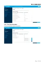
Страница 33: ...P a g e 33 64 TM1 5GM2020SG 6 4 3 Time Synchronization Time Synchronization setup for the system...
Страница 49: ...P a g e 49 64 TM1 5GM2020SG 7 6 SNMPD The section allow user to setup the SNMPD for manual configuration...
Страница 59: ...P a g e 59 64 TM1 5GM2020SG 9 3 Memory 10 Logout Click this section the router will be logged out...


