Ba
Ba
Ba
Ba
Bag I
g I
g I
g I
g I
(Contin
(Contin
(Contin
(Contin
(Continued)
ued)
ued)
ued)
ued)
Step I-17
Step I-17
Step I-17
Step I-17
Step I-17
Figure I-17
Figure I-16
Step I-16
Step I-16
Step I-16
Step I-16
Step I-16
Slide
Slide
Slide
Slide
Slide V
V
V
V
Valv
alv
alv
alv
alve Carb
e Carb
e Carb
e Carb
e Carbur
ur
ur
ur
uretor
etor
etor
etor
etorsssss
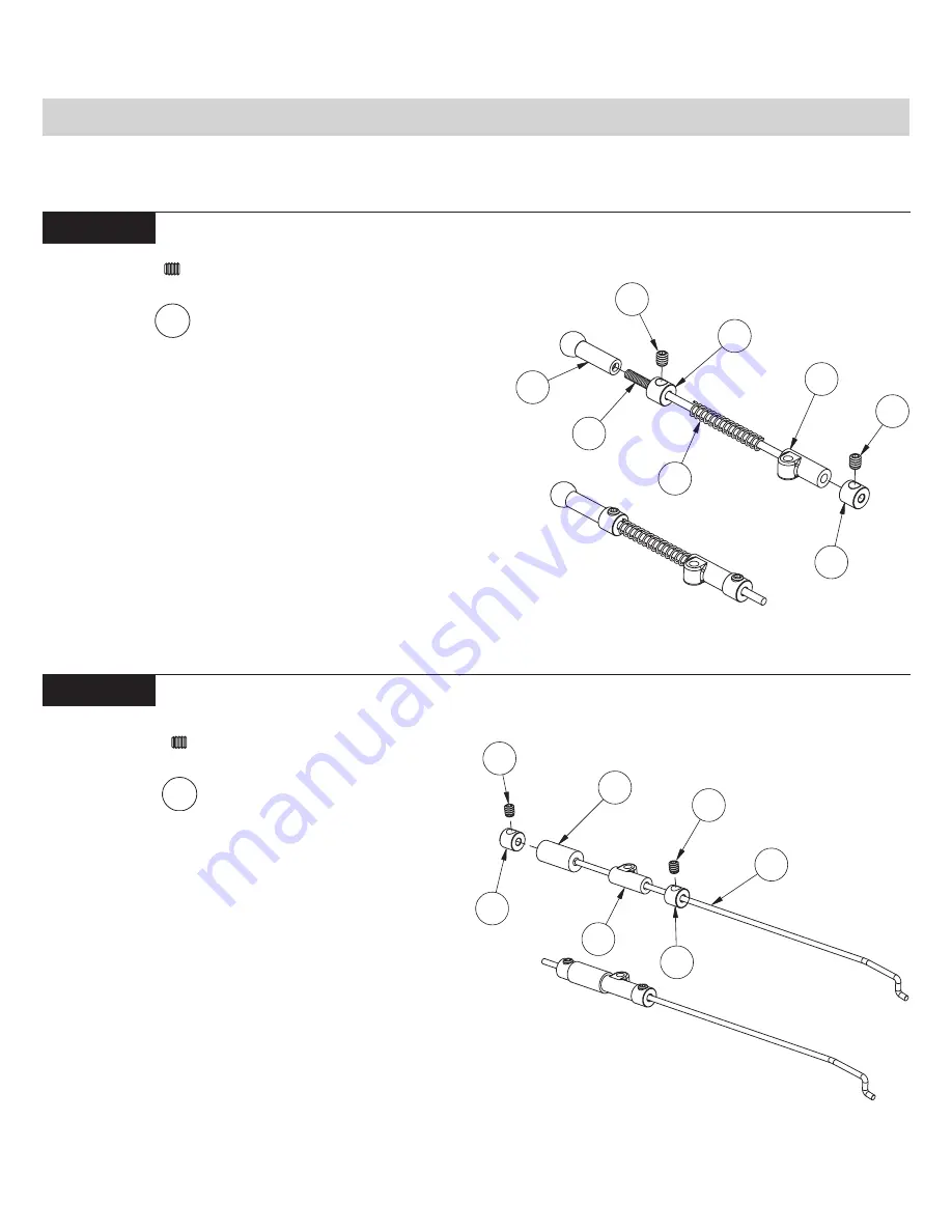
1. Thread the 4mm Ball Cup (204) all the way onto the end of the
Threaded Throttle Rod (203). Slide a Linkage Collar (192) over the
other end of the Throttle Rod, and up against the Ball Cup. Secure the
collar with a 4-40 x 1/8" Set Screw (193).
2. Place the Throttle Over-ride Spring over the rod and against
the Collar. Slide a plastic Over-ride Slider (195) onto the rod, so that
the long end is away from the Ball Cup.
3. Place a Linkage Collar over the end of the rod, so the springs
are not compressed, and secure it with a 4-40 x 1/8" Set Screw. The
collar should be positioned at the end of the rod. Final adjustments
will be made later.
1. Slide a Linkage Collar (192) over the end of the long, Brake Z-
bend Wire (197), and position it approximately 1/4" (60mm) from the
Z-bend. Secure the Linkage Collar in place with a 4-40 x 1/8" Set
Screw (193).
2. Slide a plastic Over-Ride Slider (195) onto the wire, so that the
long end is towards the Z-bend. Place a 0.5" piece of Fuel Tubing
(176) over the wire and against the slider.
3. Slide a Linkage Collar over the end of the wire until it just
touches the Fuel Tubing. Secure it with a 4-40 x 1/8" Set Screw. Once
again, final adjustments will be made later.
193
193
48
NOTE: If your engine comes equipped with a slide valve carburetor, complete
the steps in Figure I-16 through Figure I-22.
192
176
192
193
195
193
197
193
192
194
195
192
193
204
203
Throttle Linkage Assembly:
Brake Z-Bend Assembly:
Содержание XXX-NT AD2
Страница 65: ......


