background image

Содержание A-6100MKII

Страница 1: ...SANE A6100mx il Stereo Tape Deck...

Страница 2: ...0 3 V and 0 775 V which are selec table on the rear panel TABLE OF CONTENTS 1 GENERAL DESCRIPTION 3 2 SPECIFICATIONS AND SERVICE DATA 4 3 TOOLS FOR TESTING AND MAINTENANCE 6 4 PARTIAL DIS ASSEMBLY 7 5...

Страница 3: ...LEVEL Headphone Out 24 dB 48 9 mV 8 ohm 15 ips 3180p sec 50 usec NAB oo 35 yt sec IEC 7 1 2 ips 3180yssec 50 w sec NAB 100 kHz 5 kHz push pull oscillator US A Vv 145 W General 100 117 145 W 24 kg 53 l...

Страница 4: ...the Specified Input Level tereo Channel Separation 50 dB Channel to Channel at 1 kHz otal Harmonic Distortion Overall 1 0 at 1 kHz signal at 0VU NOTE As a result of continuing changes and improvements...

Страница 5: ...M AC Hewlett Packard Co Model 400E AF OSCILLATOR 4 10 Hz 100 kHz ATTENUATOR 200065 General purpose OSCILLOSCOPE 555 General purpose BLANK TAPE TEAC YTT 8013 TEAC TEST TAPE YTT 1003 7 1 2 ips YTT 1004...

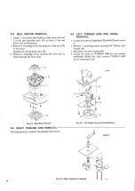
Страница 6: ...ng nuts through access slot in head pase plate and dis connect head wires See Fig 6 4 4 3 FLYWHEEL AND CAPSTAN ASS Y REMOVAL Unscrew by hand the capstan dust cap F 2 Remove 3 screws from capstan thrus...

Страница 7: ...4 4 Reel Motor Removal 4 5 RIGHT TENSION ARM REMOVAL _ _ See illustration for complete dis assembly instructions Fig 4 6 Right Tension Arm Removal ww 4 6 LEFT TENSION ARM AND GUIDE REMOVAL Loosen set...

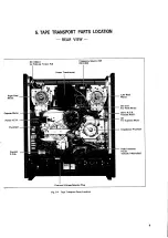
Страница 8: ...50 60 Power Transformer Right Ree Left Reel Motor Motor c9 C10 For Reel Motor Capstan Motor Servo P C B Include R931 Power P C B cs For Capstan Motor Flywheel Impedance Flywheel Peak Indicator aby P...

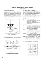
Страница 9: ...electrically while playing back the Test Tape Coarse Adjustment Without Tape HHO 0sCaeser eer By Height and Tilt screws This alignment is performed by viewing from the side without tape threaded Chec...

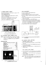
Страница 10: ...volts To rear top metal panel 6 screws change the voltage unscrew the fuse in the center of the 2 Set the power frequency selector slide switch located voltage selector plug Pull out the plug and rein...

Страница 11: ...NOTE The brake torque is actuated mechanically Torque is set by the variable Leaf Spring Force While making these measurements and adjustments be careful not to be bend the brake bands Preliminary Adj...

Страница 12: ...ut off switch right tension arm held in the ON position 3rake Torque Measurement should be made using large hub eel with a hub diameter of 4 or 10 2 cm se TAKEUP TORQUE IF WO 1 426 Fig 7 3 Torque Meas...

Страница 13: ...k for the tape tension values given in the chart below 7 If adjustment is necessary adjust the screw shown in Fig 7 7 NOTE Vertical and F F REW value is for reference only LO BACK TENSION TAPE TENSION...

Страница 14: ...Model YTT 2003 7 1 2 ips and YTT 2004 15 ips These tapes contain a highly accurate 3 000 Hz tone Con nect a digital frequency counter to either line OUTPUT jack See Fig 7 10 The indicated frequency s...

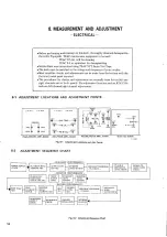
Страница 15: ...STMENT LOCATIONS AND ADJUSTMENT POINTS L ch R ch L302 C405 L201 L202 lech PB EQ BAIS TRAP Oo BIAS ADU eas VR201 vR203 H H O PB CAL R ch vriol vrio3 C406 vrio2 o VRIO4 O PBM owe L EQUALIZER MIC AMPL BO...

Страница 16: ...eck Play the 16 kHz 10 dB Test Tone in section 2 of the Test Tape 5 Slowly rotate the Azimuth screw until maximum signal is read on the VTVM 6 Connect an Oscilloscope to the OUTPUT jacks 7 Adjust the...

Страница 17: ...dB at 10 kHz NOTE If the response is not uniform the head should be checked for accumulated dirt or oxide If clean head azimuth must be readjusted 8 8 DIFFERENCE LEVEL CHECK 2T PLAY AND 4T PLAY 22 Wi...

Страница 18: ...ibed in 8 10 Adjust REC M CAL VR302 305 for 0 VU reading on VU Meters 8 12 CHECK OUTPUT LEVEL SELECTOR SW on REAR PANEL 7 Set the controls as described in 8 10 Specified Input Level 8 dB 8 Switch OUTP...

Страница 19: ...be rotated slightly with a pause to see the effect FINE ADJUSTMENT 7 Connect a VTVM to the OUTPUT jack and an AF os cillator to the LINE IN jacks Set the oscillator to 10 kHz at 28 dB 30 8 mV 8 Begin...

Страница 20: ...on again ES oy n I Ss 400 500 IK FREQUENCY IN Hz Fig 8 14 Frequency Response B OVERALL EQ SW BIAS SW 1 eee 2 20 Apply signal swept from 30 Hz to 20 kHz 8 dB 21 30 8 mV to the LINE IN jacks and record...

Страница 21: ...2 CHANNEL SEPARATION Tape SPEEDSW HIGH 15 ips EQ BIASSW 2 64 1 1 Be sure tape YTT 8013 is completely bulk erased prior to doing these checks 2 Apply a1 kHz signal at 18 dB 97 5 mV to L ch 3 Place deck...

Страница 22: ...PLAYBACK RECORD 9 SIMPLIFIED SCHEMATIC AND LEVEL DIAGRAMS RECORD PLAYBACK gig E Fig 9 1 Simplified Schematic Diagrams Fig 9 3 Level Diagram Record...

Страница 23: ...tina G auaighGrete ting 2 drops Remove the dust cap for access to the oil pit Capstan Motor 2 0 0 eee eee eee 0 5 cc Maximum to fill oiling tube NOTE Excessive oiling will scatter oil inside the deck...

Страница 24: ...6 02 eee eee 23 3 TIMER P C B 2 ee eee 34 4 TENSION SERVO CIRCUIT 5 35 AMPLIFIER SECTION 1 PLAYBACK EQUIALIZER AMPLIFIER 38 2 LINE AMPL PHONE AMPL 29 3 MIC AMPLIFIER 2 222 200 eee eee eee 40 4 RECORD...

Страница 25: ...ase current will flow through Q2 along the route of Vec R3 RS R4 Q2 and Q 2 will go to ON state Since when Q2 goes to ON state Q terminal goes to a Low level and even if the SET terminal is opened the...

Страница 26: ...F and point B is at a High level At this time point B is at 24V Point D is approximately 1 2V and C717 is charged to to polarity as shown in the Figure above Route 1 Route 2 As C716 continues to charg...

Страница 27: ...5 SR765 R764 D736 i R762 REC SIGNAL 5 o j42av TO AMPLIFIER fe 9727 0709S rec R76 R728 4 R FF G R760 e R768 ud K WS D737 C UO t24v Q 0726 LAM Spi e__ RECORD R763 ee D738 D715 24v R77I R770 STOP SIG R73...

Страница 28: ...Q727 via route 10 and it will 0 ON and the PAUSE LED will light If the PAUSE key s released the reset signal to the Play Flip Flop along route disappears and if the p play key is pressed the deck will...

Страница 29: ...GH Q709B se a wan ea HIGH Q7I0B LOW 05S OSC als ii ql LOW HIGH Q7138 LOW HIGH Q714B Low sae aa Se ee REC F F LOW HIGH HIGH LOW ae _ HIGH w Al oO ol LOW men CH OFF Eee pee aad REC LED on ae aaa GE RSET...

Страница 30: ...ke Solenoid The F FWD and REW circuits are completely symmetrical There fore when the q q REW key is pressed the same process occurs as in F FWD operation and the Brake Solenoid Relay K3 and Relay K4...

Страница 31: ...ter the dely time of the monostable multivibrator finishes Q718 will go OFF then Play mode will begin F FWD REW DELAY STOP PLAY Approx 3 Sec T 1246 Fig 10 F FWD REW Play Timing Chart 6 STOP MODE The S...

Страница 32: ...Brake Solenoid and the Capstan Solenoid will be energized at the same time the Capstan Solenoid will also use this drive circuit RIGHT REEL MOTOR K2 al Ki Ol K2 K4 OFF Fig 13 Reiay Circuit 1 PLAY MODE...

Страница 33: ...metimes unusually large tape tension may occur In order to prevent this unusual tape tension from occuring during acceleration as explained above the take up motor torque is held down In order to prov...

Страница 34: ...he Servo Amplifier output circuit is constructed as shown in Fig 19 The alternating current motor current which is supplied to the Bridge Circuit produces current flow in the path indicated by the sol...

Страница 35: ...ECTING SIG INPUT BS R9II Q TO 0725 R9I4 REW MODE HIGH Ov TO Q7Ig PLAY MODE HIGH TO 0723 STOP MODE HIGH R928 gil R92 COI cae RSalg ee tie c9i4 Qgi8 16 oi R935 cgl2 ae DIE R927 aE os 0 Roe R936 AC IN pg...

Страница 36: ...c Q7 19 B Q7I9 C Q720 B Q720 C Q72i Cc Q722 B Q72e C Q723 C Q724 68B Q724 C Q725 8B Q725 C Q726 8 a7e6 Cc Q7e7 8B Q727 C Q728 8B Q72B C Q7e9 Q730 C REC MODE SW BASIC TIMING CHART FAST FWD REC Rewino P...

Страница 37: ...ll have a direct coupled D C operating voltage potential which will go up Therefore if preparations for high voltage potentials are not made dynamic range will be narrow and distortion SPEED 502 1 CHO...

Страница 38: ...alue becomes more than 4 5 Mohms Since the amplifier input impedance is very high the selection of the playback head load resistor can be freely made and the optimum load can be obtained At 20 kHz the...

Страница 39: ...e negative feedback circuit in order to prevent the gain of the amplifier from changing when the level controls are rotated Facing this circuit is a 10 kohm potentiometer On the in put side there are...

Страница 40: ...because the slower the tape speed espe ally at high frequency sounds the lower the tape satura on level will be 6 BIAS OSCILLATOR The control circuit for the Bias Oscillator is shown in Fig 8 ON OFF...

Страница 41: ...the REC Ampli fier to drive the Record Head Route 3 This path is connected to the dummy coil For example when recording only the L channel since the R channel erase head and record head are not conne...

Страница 42: ...ee te P Ly LIU 1 REC LED ol eral Fe pa chill ee el Jol rn Sia 1 1 Q727 073 2SC945 LK Q709 Q7lo a7l4 2SA733 P 2SC945 LK 2 0235 0 ow PAUSE LED CAPACITOR in PCB REMOTE L CONTROL J RC 70 CONTROL PCB NOTES...

Страница 43: ...LK enaver at Qgi8 a 2SA666 IS R762 10k 2508 280665 RI7 28C 1318 S i 9 y7 co RIGHT REEL MOTOR 10 POWER SUPPLY PCB 215 0 14120 CAPSTAN MOTOR 4 ov A 00v B SAFETY SW 27 pare ee ee es 33 GENERAL EXPORT S 1...

Страница 44: ...raid soa RI ne ap Uae ae Riga RI46 k 36k RI49 fasv tk RISO 23 7 tC RIS E 9 ROUT Cc 2 sore 101 104 2SCI345 E or 9202 0205 2SA7SO E 0401 9403 2SCI317 S of 28C1345 F 9203 0206 25C828 s or 28C1318 S or ee...

Страница 45: ...Put X HIGH 4 5V LOW 12 8V R312 R313 47 100k 080 sRBIS S3OI6R 1317 S of 1318 S or 1318 AS S 168 828 S or 36 G 10 BL 10 BL 10 i Falontlestae oS ae Pe ho rtenore __ A6100mI Revision oaTe CHANGE RO rie MR...

Страница 46: ...r nearest TEAC Autho tized Service Center or directly from the TEAC office the address of which is written on the back cover When ordering parts always include the following information 1 MODEL 4 DESC...

Страница 47: ...1 EXPLODED VIEWS AND PARTS LIST SECTION EXPLODED VIEW 1...

Страница 48: ...e Head Base Spring Head B Spring Head D Plate E R P Head Spacer Erase Head Spacer Head A Head Playback 2T 2CH Head Playback 4T 2CH Head Record 2T 2CH Head Erase 2T 2CH Shield Head A Bracket Protector...

Страница 49: ...EXPLODED VIEW 2...

Страница 50: ...apacitor MP 7 1 5 mfd x 2 Capacitor MP 7 mfd x 2 Resistor Wire Wound 100 ohm 30 HA Bracket Resistor Retainer Cord Stud Reet Motor Chassis Reel Motor Chassis Reel Motor A Panel Top A Reel Table Assy Be...

Страница 51: ...EXPLODED VIEW 3 Se 2 SC M4x6 naa BSA _ 3 BsA M3x8 5 M4xio...

Страница 52: ...8 mfd 250V 3 28 50237521 Plate Capstan Motor 3 29 50123984 Fan 3 30 50701341 Motor Capstan 3 31 50706211 Cushion Rubber 3 32 50332790 Spacer Rubber Cushion 3 33 50124003 Pulley Motor 50Hz 60Hz GENERAL...

Страница 53: ...EXPLODED VIEW 4 3 W8xt0 5 N t a GEe00dGe ie f x A qy 33 B Ww...

Страница 54: ...Bracket Lever Switch Switch Push Retainer Cord A Mask Lever Switch PC Board Assy EQ PC Board Resistor Carbon 2 2k ohm 1 4W 5 x 2 Capacitor Mylar 0 015 mfd 50V 5 x 2 Switch Lever Switch Lever Switch L...

Страница 55: ...EXPLODED VIEW 5 US A CANADA 10...

Страница 56: ...AC Power U S A CANADA 5 20 50430010 Connector DIN 5 21 55501240 Bracket PC Board 5 22 50233760 Plate PC Board 5 23 51685370 PC Board Assy MIC Playback EQ Ampl 5 24 51681082 PC Board Assy Line Out Pho...

Страница 57: ...2 PLAYBACK EQ MIC AMPL 1 2 KU cn Ri2IY Rl24 47k i Ria sen 2122 56k CII6 470p 12k BoC E curd R13Q_ 180k P 349 LINE PHONE AMPL 2 2 R208 56k SBk R204 56 t R212 C210 10 25V C2l3 47 10V see C227 100 25V R2...

Страница 58: ...BIAS OSC UNIT 2 3 RECORD METER AMPL PC BOARD m RiaeS age SE OIS 35VE ic338 peperainny i Shov 4 D 3K R366 22k see 350 Ivasv I eee Bl B65 62k oN C405 80p MAX P 355 1 P 353 2 5 TIMER PC BOARD xeRS75_ 100...

Страница 59: ...2 6 CONTROL PC BOARD Alb 91Ze 14...

Страница 60: ...2 7 PEAK INDICATOR PC BOARD R826 18k R825 IBk R820 15k REIS 15k BIG 39k R938 220k aM R937 680 2W P 362 0 5 3W 15...

Страница 61: ...16 2 11 POWER SUPPLY PC BOARD 2 cr n x OI7 SR34 200HM 0 17400V P 423...

Страница 62: ...Mica 51700820 Elec 50549740 Elec 50554230 Elec 50543820 Dip Mica 50547560 Dip Mica 51700820 Elec 50548020 Mylar Non Flammable Non Flammable 10 mfd 47 mfd 470 pfd 10 mfd 100 mfd 100 mfd 22 pid 470 pfd...

Страница 63: ...R333 50571240 56k ohm C213 C226 50555540 Elec 47 mfd 10V R303 R334 50571240 56k ohm C227 50554170 _ _Elec 100 mfd 25V R304 R335 50571220 47k ohm R305 R336 50571200 39k ohm VARIABLE RESISTORS R306 R33...

Страница 64: ...Mylar 0 001 mfd 50548780 Mylar 0 001 mfd VARIABLE RESISTORS 50533960 50533960 50533960 COILS 50566670 50566300 50566590 Semi fixed 33k ohm B Semi fixed 33k ohm B Semi fixed 33k ohm B Record EQ Trap 3m...

Страница 65: ...2473VE Zener 0226 2A 182473VE All resistors are rated 5 tolerance 1 4 watt and of carbon type unless otherwise noted R701 R702 R703 R704 R705 R706 R707 R708 R709 R710 R711 R712 R713 R714 R715 R716 R71...

Страница 66: ...OUS P701 50438450 Connector Socket 10P J702 51220120 Connector Plug 10P 2 7 PEAK INDICATOR PC BOARD REF NO Q801 Q802 Q803 0804 Q805 Q806 D801 D802 D803 D804 R803 R804 R805 R806 R807 R808 R809 R810 R81...

Страница 67: ...PC Board TRANSISTORS Q911 Q917 51450360 28C945 LK Q918 50424210 2SA666I S ag19 51450810 2SD665 DIODES D911 50425170 18 2473VE D912 50422640 Zener 0227 5A 0913 D916 51430890 WO03C RESISTORS All resist...

Страница 68: ...R5 R6 R7 R8 R11 R12 R13 R14 R15 R16 R18 C1 c2 C3 c4 C5 c C7 C11 C12 C13 Zi Z12 221 Z22 K1 K2 K3 K4 51843060 Cement 3 3 ohm 2W 50518040 Cement 0 5 0hm 3W 50520340 Cement 1 5 0hm 3W 50570940 3 3k ohm 50...

Страница 69: ...nk Cuma Hex Socket Head Screw Setscrew Flat Point Oval Countersunk Hex Socket pp oneneae Setscrer Cup ony Round Head Slotted Socket Wood Screw Setscrew Flat Point Flat Countersunk E Ring Wood me D Ret...

Отзывы:

Похожие инструкции для A-6100MKII