background image

Содержание A-4010GSL

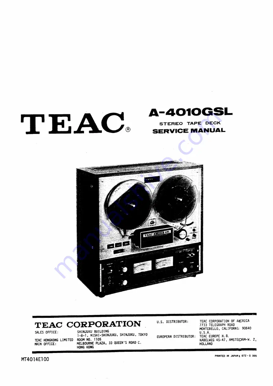
Страница 1: ...EAC CORPORATION OF AlERICA TEAC CORPORATION 7733 TELEGRAPH ROAD SHINJUKU BUILDING One 8 1 NISHI SHINJUKU SHINJUKU TOKY S A one as pee EUROPEAN DISTRIBUTOR TEAC EUROPE N 8 MELBOURNE PLAZA 33 QUEEN S RO...

Страница 2: ...lignment procedures schematic diagram and parts replacement information and the prop er procedures for obtaining necessary repair parts SCOPE TABLE OF CONTENTS SL GSL FUNCT IONAL COMPARISON CHART SERV...

Страница 3: ...operated quarter track stereo open reel tape deck with automatic reversing during playback The A 4010GSL is also designed for LOW NOISE HIGH OUTPUT tapes The TEAC A 4010GSL is a modernized version of...

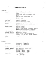
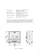
Страница 4: ...pole dual speed hysteresis synchronous motor for capstan drive 6 pole eddy current motors for reel drive 0 07 at 7 1 2ips 0 09 at 3 3 4ips Wow and flutter measured according to weighted NAB standard u...

Страница 5: ...unweighted noise Cross Talk Rejection 40dB channel to channel at 1kHz 35dB adjacent track at 100Hz Erase Efficiency 7OdB or more at 7 1 2ips A These specifications are indispensible information and ar...

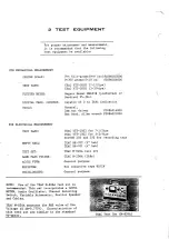
Страница 6: ...Meguro Model MK665B preferred or Sentinel FL 3D 1 Capable of 0 to 5kHz indication General 2mm nut driver 5086014000 Hex head Allen wrench 5086021000 TEAC YTT 1003 for 7 1 2ips TEAC YTT 1002 for 3 3 4...

Страница 7: ...a...

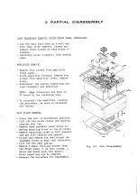
Страница 8: ...d in PC board by two retaining nuts To reinstall the amplifier reverse the procedure be sure to reconnect the cables FACE PLATE REMOVAL Place the unit in horizontal position Pull off the pinch roller...

Страница 9: ......

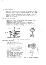
Страница 10: ...se the procedure for reassembly Position the brake drum from the edge of the brake band as shown REEL HEIGHT REEL TABLE ASSY 9339 M O333 Fig 3 2 Reel Table Assy Replacement CAPSTAN MOTOR REPLACEMENT S...

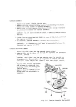
Страница 11: ...erse above procedures IMPORTANT A clearance of 0 02 must be maintained between the flywheel and capstan assembly BELT REPLACEMENT Remove the rear cover and the capstan thrust plate Capstan belt can be...

Страница 12: ...etnuts each head can be taken off easily one screw for erase head Slots provide access through the plate to these setnuts CAUTION Do not touch other set screws Note the position of the wires on the ci...

Страница 13: ...btain this height IMPORTANT After completing the height adjustment make certain head surfaces are parallel with tape guide surfaces when viewed from the side PLAYBACK HEAD The reverse playback head po...

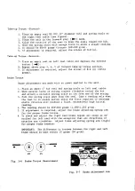
Страница 14: ...capstan solenoid plunger PINCHROLLER Vom 0 113 Fig 5 1 Pressure Measurement Fig 5 2 Pressure Adjustment Nuts FLUTTER TAPE SPEED MEASUREMENT _ Flutter should be measured in playback mode using a TEAC...

Страница 15: ...is in steady motion The spring scale reading should be 50 52 grams torque 2501260 g cm 7 If adjustment is required move the slider of R 6 D until cor rect tension is obtained Holdback Tension Reverse...

Страница 16: ...easurement Place an empty 4 hub reel and spring scale on left reel table Wind several turns of string counter clockwise around the hub and attach a suitable spring scale to the free end of the string...

Страница 17: ...AST WIND TIME NOTE Clean all tape guide components and check for proper AC line voltage Using a 1 200 feet tape on a 7 reel the fast wind time fast forward or fast rewind should be 100 seconds or less...

Страница 18: ...checks and adjustments unless otherwise indi cated are for the left channel at 7 1 2ips The same pro7 cedures are to be applied to the right channel and 3 3 4ips tape speed All controls mentioned in t...

Страница 19: ...ndication is obtained on the level meter NOTE If during playback a slight pressure on the heads re sults in a rise of the reading of the level meter head alignment readjustments should be accomplished...

Страница 20: ...sturb this setting until the remaining adjustments have been completed VU METER CALIBRATION PLAYBACK 12 While playing the 400 Hz tone 1 THD in section 1 of the test tape adjust VR 108 208 for a readin...

Страница 21: ...nsion arm should be in ON position Place the unit in the PLAY mode Bm the tape will not move 2 3 The level meter connected to the OUTPUT jacks should indicate 56 dB or less a0 4 This corresponds to a...

Страница 22: ...no adjustment only an operational check After completing the check rotate MIC controls fully counter clock wise to eliminate noise from mic jacks or mic preamplifiers SPECIFIED INPUT LEVEL SET 8 Appl...

Страница 23: ...BLOCK DIAGRAM AND ADJUSTABLE PARTS LOCATION 24d8 8Q LOAD FORMARD PB FILTER PLAY BACK HEAD Pee Z N REVERSE VRIO3 203 xX ERASE H BIAS OSC...

Страница 24: ...lace the MONITOR switch to SOURCE and adjust the AF oscillator to obtain a signal of 15 dB below the specified level The level meter will indicate 23 dB After this is set turn MONITOR switch to TAPE p...

Страница 25: ...monitor amplifier and under normal no signal conditions bias leakage voltage should not be present at the OUTPUT jacks Place the unit in RECORD with no signal applied Connect a VIVM to the junction o...

Страница 26: ...he capacitors clockwise until 7 After completing this adjustment return BIAS EQ LEVEL switch to HIGH position 2 Fig 6 11 Bias Characteristic RECORD LEVEL SET HIGH POSITION 1 The OUTPUT controls must b...

Страница 27: ...OTE If the response is not uniform the heads should be checked for accumulated oxide and dirt Then if no dirt is found the equalization coils L 102 202 should be adjusted If further adjustment is requ...

Страница 28: ...jacks 3 Place the unit in the record mode with no signal applied BIAS EQ LEVEL switch in HIGH position NOTE Noise readings when taken while recording may be affected by the bias signal which could be...

Страница 29: ...Apply a 1 kHz signal at 0 dB to the LINE IN jacks Place the unit in record mode and record this signal Rewind the recording to the beginning and remove the AF oscil lator from the LINE IN jacks _ Plac...

Страница 30: ...k use The following maintenance procedures are to be carried out after parts replacement after extended periods of use or at overhaul When installing new parts always clean the mechanism thoroughly us...

Страница 31: ...o be lubricated should be cleaned and old oil and dirt re moved before relubricating Observe instructions as to type of oil points to be lubricating Motors should be lubricated immediately after use w...

Страница 32: ...inor maintenance or inadequate supplementary or associated equipment If your unit fails to perform properly refer to the handbook of operation clean and lubricate as per the instructions Carefully che...

Страница 33: ...Pinch roller pressure incorrect VOLTAGE SELECTOR switch in wrong position Diode D 2 Capacitor C 4 Capstan solenoid L 2 The normal DC resistance of the solenoid is approx 1 3k Right reel motor assy Wir...

Страница 34: ...nment Tape faulty Heads dirty Heads worn Playback level adjustment Head switching relay K 7 Head out of alignment Interconnecting cables loose or out Heads dirty Record ampl circuit Bias oscillator as...

Страница 35: ...ms may vary with the country area in which it was pur chased and for different models of equipment The warranty terms are fully described in the enclosed warranty card Please read the card for complet...

Страница 36: ...svia 02 0 N apoe AOL loz GVSH 3SVY3 10IDA lzZ dIH SINANOdHOD LNIKISACAY WAAL G MaHS TANNVIND LUDTE TINNVID 1337 OL WIATE SYZGHAN TORHAS GALVNDISaG aINOd LOA SLE O OP O ROTLISOd GIIdDadS INOD Lndinod L...

Страница 37: ...RIGHT REEL MOTOR COMPONENTS LOCATION TAPE TRANSPORT Ll S6 L2 sl LEFT REEL MOTOR CAPSTAN MOTOR K2 C26 27 29 30 32 33 PAUSE PC ASSY TOP VIEW...

Страница 38: ...MANUAL CHANGES REVISIONS for the models in this manual when appropriate This sheet is in loose leaf form and should be filed behind this page for convenient reference...

Страница 39: ...able through your nearest TEAC dealer or directly from the TEAC office Changes are constantly being made to make TEAC products better and more reliable Therefore when ordering parts always include the...

Страница 40: ...9099 999093909 0 990999999 909 9999990 99909 99994 9999993 6 999 999900799 rrr 9 093039995 999999999 09999 099 6 2999 99090 S o 0a 9939099 990909979 199999999 9999909 oaeee 9999909 4 99999 0 00 990 90...

Страница 41: ...5936 50287841 50283830 50278560 50287830 TRIM PARTS DESCRIPTION Reel Assy Head Housing Name Plate A 4010GSL Name Plate 4010GSL Panel Dress Dust Cap Pinch Roller Assy Washer Tension Arm Guide Assy Left...

Страница 42: ...EXPLODED VIEW 2 Ap 401 0GSL ABOVE MAIN CHASSIS 1...

Страница 43: ...1140 50272480 50443210 50251100 50272591 50112456 50331930 PARTS LIST 2 A 4010GS5L ABOVE MAIN CHASSIS 1 DESCRIPTION lst 2nd Head Assy Push Holder Assy Lever Assy A Lever Assy B Lifter Lever Assy Arm L...

Страница 44: ...EXPLODED VIEW 3 A 4010GSL ABOVE MAIN CHASSIS 2 0 be VI do Geali...

Страница 45: ...ST3 A 4010G6S8SU ABOVE MAIN CHASSIS 2 DESCRIPTION 2nd Knob Reel Lock B Spring Slip Reel Lock Shaft Reel Lock B Reel Sheet Reel Table Spring High Adjust ie Brake Drum Screw High Adjust Lever Brake A Sp...

Страница 46: ...EXPLODED VIEW 4 a 4010GSL BELOW MAIN CHASSIS...

Страница 47: ...PARTS LIST4 A 4010GSL BELOW MAIN CHASSIS DESCRIPTION 2nd Fan Capstan Capstan Motor Assy Reinforcing Plate Rubber Cushion Plate Capstan Motor Pulley Capstan Motor Transformer Power 100 117 200 220 240...

Страница 48: ...EXPLODED VIEW 5 A 4010GS BACK PANEL PARTS...

Страница 49: ...e Holder LOOV only Fuse Holder 117V only Fuse Holder 100 117 200 220 240V Fuse 2A Mounting Plate 100 117 200 220 240V Mounting Plate 100V 117V GND Terminal Cover Back Face Plate Right Cap MP 1000uF 35...

Страница 50: ...EXPLODED VIEW 6 A 4010GSL HEADS AND CAPSTAN 3xi2 3 M3x1i0 M4x40 M SN mm EAD...

Страница 51: ...ead 50663030 Head Erase 50220452 Spring Playback Head 50133591 Mount Plate Record Head 50675320 Spacer Head 50667300 Head Playback Ferrite 50675650 Case Shield A 50220420 Spring Record Head 50667210 H...

Страница 52: ...EXPLODED VIEW 7 As 4010GSL CONTROL BUTTON ASSY...

Страница 53: ...50272561 Switch Mounting Chassis 7 5 50220840 Spring 6 50449430 Push Plate Assy 7 50446130 Switch Micro V 1A44 8 50446101 Switch Micro V 1A10 9 50449450 Push Plate Assy 7 10 50210060 Shaft M3 x95 J 11...

Страница 54: ...EXPLODED VIEW 8 a a4010GSL PREAMPLIFIER CHASSIS FRONT S 6 yep fo ool lz g axew...

Страница 55: ...0560 50241700 PREAMPLIFIER CHASSIS FRONT DESCRIPTION Ampl Chassis Assy Face Panel Sash VU Meter Knob A Knob B Double Potentiometer Double Potentiometer Switch Lever Sheet Lever Knob Knob Switch Jack 1...

Страница 56: ...XPLODED VIEW 9 A 4010GSL PREAMPLIFIER CHASSIS REAR...

Страница 57: ...11 50432100 Connector 7P 9 12 50436190 Socket 11P 9 13 50489041 Bias PC Board Assy 9 14 50233800 Mounting Bracket 9 15 50488540 Bias Oscillator Assy 9 1 50234633 Ampl Chassis Assy 9 2 50266410 Name Pl...

Страница 58: ...are available through your nearest TEAC dealer or directly from the TEAC office Changes are constantly being made to make TEAC products better and more reliable Therefore when ordering parts always i...

Страница 59: ...PC BOARD A 4010GSL PREAMPLIFIER BIAS SW rr x g 2 2 BIAS SW BIAS SW MIK JK J201 EQRELAY MIC JK Jton Mic VR 108...

Страница 60: ...DES or 2SC367 BL or 2SC369 BL 50442570 SIBO1 06 or FR2 06 50442570 SIBO1 06 or FR2 06 CARBON RESISTORS AND CARBON TYPE UNLESS OTHERWISE NOTED R101 201 R102 202 RL03 203 R104 204 R1LO5 205 R106 206 R1L...

Страница 61: ...0 R171 271 R172 272 TEAC 50515540 50515280 50515170 50515350 50519960 50519790 50518240 50518240 50519810 50518250 50515570 50518260 50515310 50515350 50518270 50519820 50515460 50518280 50515350 5051...

Страница 62: ...0554050 50554050 50554230 50543410 50548540 50554050 50548240 50546030 50543120 50548290 50548270 50554170 50546190 50548320 50554030 50554050 50554230 50543330 50543340 50548420 50554510 50554670 505...

Страница 63: ...0 Trimmer Resistor 10kQ2 B 10 VRLO4 204 50533570 Trimmer Resistor 220k2 B 10 vR105 205 50533460 Trimmer Resistor 4 7k2 B 10 VR1O7 207 50533450 Trimmer Resistor 1 5k2 B 10 VRLO8 208 50533470 Trimmer Re...

Страница 64: ...0488540 PC Board Assy Bias Osc T301 50563120 Coil Oscillator Q301 302 50423880 Power Transistor 2SC 971 C301 50554180 Electrolytic 220uF 25V C302 50548040 Mylar 0 1uF 50V C303 50548210 Mylar 0 0022uF...

Страница 65: ...RCUIT REF NO 2nd 50482632 PC Board Assy VC102 202 50547040 Trimmer Capacitor 10v100pF VR1O9 209 50533560 Trimmer Resistor 22k2 B 10 C148 248 50548130 Mylar 0 0047uF 50V TRIMMER RESISTOR SOURCE LEVEL A...

Страница 66: ...REF NO 2nd 50488660 PC Board Assy Reverse RL K2 3 50610730 Relay 4I DC 100V K6 50610280 Relay 1M 100E02M C5 50555210 Electrolytic 22uF 160V C7 9 50554510 Electrolytic lOuF 35V C10 11 12 50548390 Metal...

Страница 67: ...ORMER LOOV FUSE POST C3470 35V 048232290 AG M 0208 TEAC PARTS NO CIRCUIT DESCRIPTION 50490580 PC Board Assy Power Supply D1 50422220 Silicon Stack SIBO2 BOI D2 50442570 Diode SIBO1 06 or FR2 06 C2 3 5...

Страница 68: ...Guvog od auyow ad a ivod od Try 49 MUVOM Od AIN 9u0 cY GYVOe Sa aSNvd Madd AOST 49001 999 ON PyA TY Lsva Guvoe Od 3SNVd PEO aus as NOLLVYSdO EG GIONaT1I0S 3xVaT GIONI10S NVLSavd DESCRIPTION PC Board A...

Страница 69: ......
Страница 70: ...niature Relay LC1 C 48V K10 50610800 Miniature Relay LC1 C 24V C43 50 51 50548 90 Metallized Mylar 0 1yuF 400V c49 5055530 Electrolytic 22uF 160V C52 50554000 Electrolytic 47uF 160V D10 11 50442570 Di...

Страница 71: ...A91 01 49D AS2z t ASZ 1t 2200 0 EZOLID 6zz SUID I voeD B ME ADI EE Betis Bose i eeae J WoL svg a walwa ad Ay 126982 A EELOSZ WOLVTUDSO OED dWY JNOHd avaH ms 4 y UID oz 004 qcoee es etl oie rea tie x...

Страница 72: ...cai ca9 3 RIGHT REC Tao M C30 1 it o SUV O REVERSE RL Cso 22 160V it PLAY HEAD a K2 Cc C 43 Ks Q FWD 3 Kio rs OL FT O 4q DELAY RL cSt ce 100 160V eames ey epery a Rio 10 37 REV w FAST SOL Rig 4 7K 3H...

Отзывы: