TE CONNECTIVITY SENSORS
/// LDM-1000 OPERATION MANUAL
P/N 09290100-000 REV. C
05/2016
Page 1
OPERATION MANUAL
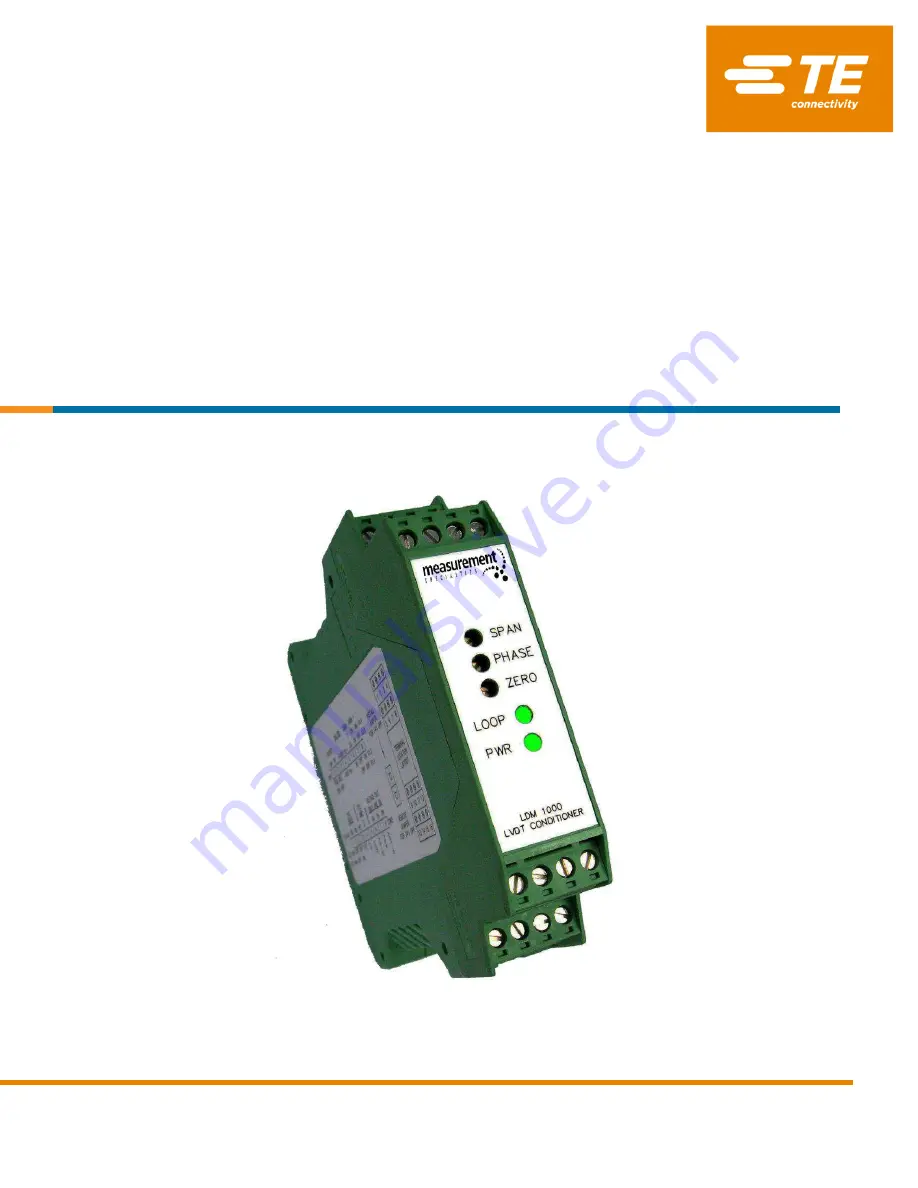
LDM-1000
LVDT/RVDT Signal Conditioning Module
Страница 1: ...TE CONNECTIVITY SENSORS LDM 1000 OPERATION MANUAL P N 09290100 000 REV C 05 2016 Page 1 OPERATION MANUAL LDM 1000 LVDT RVDT Signal Conditioning Module...
Страница 2: ...s 1 Introduction 3 2 Product Specifications 3 3 Product Description 4 4 Initial Setup Procedure 4 4 1 Supply Voltage 5 4 2 Internal Switches 6 4 3 Oscillator Frequency 6 4 4 Oscillator Sync Mode 7 4 5...
Страница 3: ...ise ripple 5mV RMS maximum Current output noise ripple 25 A RMS maximum Current loop resistance 700 maximum with 18 to 30VDC supply voltage Frequency response 250 or 1000Hz 3 dB 3 pole Butterworth DIP...
Страница 4: ...hese plug in strips are keyed to prevent improper connections in the unlikely event that the LDM 1000 should require field replacement The next few pages will take you step by step through the simple...
Страница 5: ...e full scale linear or angular range over which you intend to perform the calibration Analog output signal required by your application 4 1 Supply Voltage The LDM 1000 supply voltage range is 18 30 VD...
Страница 6: ...1 2 3 4 5 6 7 8 Frequency Switch Position Switch ON INT 1 VRMS 0 5 5 0 10 10 kHz ON ON Switch OFF EXT 3 VRMS Only one switch ON 5 kHz OFF ON 4 to 20mA output works with any setting 2 5 kHz OFF OFF Not...
Страница 7: ...with a robust sine wave oscillator it is rated for a maximum drive current of 25mA RMS with a voltage amplitude of 1 or 3 VRMS Therefore you will need to know the LVDT RVDT transducer input impedance...
Страница 8: ...LDM 1000 LVDT RVDT Signal Conditioning Module TE CONNECTIVITY SENSORS LDM 1000 OPERATION MANUAL P N 09290100 000 REV C 05 2016 Page 8 5 Dimensions and Wiring Terminals...
Страница 9: ...LDM 1000 LVDT RVDT Signal Conditioning Module TE CONNECTIVITY SENSORS LDM 1000 OPERATION MANUAL P N 09290100 000 REV C 05 2016 Page 9 6 Connection Diagrams...
Страница 10: ...l scale position you used in your calculation in Setting the Amplifier Gain 4 Adjust the front panel PHASE potentiometer in the direction that increases the DC output signal until the maximum output i...
Страница 11: ...Sensor Technologies AST TE Connectivity TE Connectivity logo and EVERY CONNECTION COUNTS are trademarks All other logos products and or company names referred to herein might be trademarks of their re...