83-517-000 Rev.
A
56
6.5
RESISITIVE PROGRAMMING OF OUTPUT VOLTAGE AND CURRENT LIMIT
For Remote
Resistive
programming, internal current sources, for Output voltage and/or Output current control,
supply 1mADC through external programming resistors connected between J1-9 & J1-22 (for VPGM) and J1-10
& J1-23 (for IPGM). The voltage across the programming resistors is used as a programming voltage for the
power supply. Resistance of 0~5kohms or 0~10kohms can be selected to program the Output voltage and
Output current limit from zero to full-scale.
A variable resistor can control the output over its entire range, or a combination of variable resistor and
series/parallel resistors can control the output over a restricted portion of its range.
Perform the following procedure to set the power supply to
Resistive
programming:
1. Press the AC Input ON/OFF power switch to the
OFF
position.
2. Set DIP-switch SW1-1 to the
UP
position for Output voltage external programming and SW1-2 to the
UP
position for Output current limit external programming.
3. Set SW1-3 to select the programming resistor range according to Table 6-4.
4. Set SW1-7 to the
UP
position for Output voltage
Resistive
programming and SW1-8 to the
UP
position for
Output Current limit
Resistive
programming.
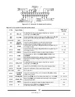
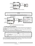
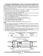
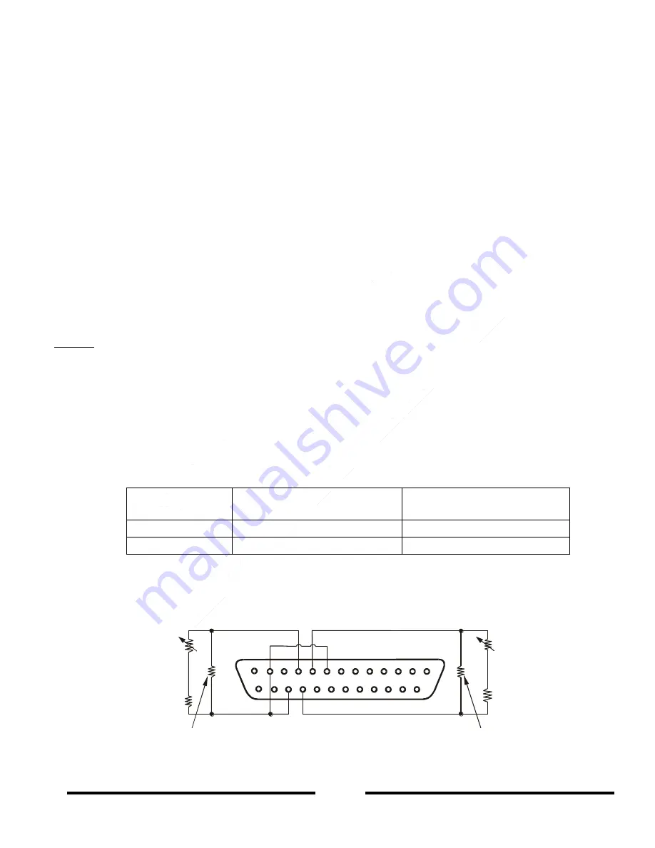
5. Connect a wire jumper between J1-8, J1-12 and J1-23 (refer to Table 4-4).
6. Connect the programming resistors to the mating plug of J1 as shown in Figure 6-2.
7. Set the programming resistors to the desired resistance.
8. Press the AC Input ON/OFF power switch to the
ON
position.
9. Press the
OUT
button to turn the power supply
ON
.
10. Adjust the resistors to change the power supply Output voltage and Output current.
NOTES:
1. SW1-4, -5, -6 and -9 are not required for Remote
Resistive
programming. Their settings can be determined
according to the application requirements.
2. The control circuits allow the user to set the Output voltage and Output current limit up to 5% over the
model-rated maximum value. The power supply will operate within the extended range, however it is not
recommended to operate the power supply over its Output voltage and Output current rating, and
performance is not guaranteed.
3. To maintain the temperature stability specification of the power supply, the resistors used for programming
should be stable and low noise resistors, with a temperature coefficient of less than 50ppm.
4. When Remote Resistive programming is used, the front panel and computer control (via the J3 serial
communication port) of Output voltage and Output current are disabled.
SW1-3 setting
Output Voltage programming
VPGM (J1-9)
Output Current programming
IPGM (J1-10)
UP
0-10kohms
0-10kohms
DOWN
0-5kohms
0-5kohms
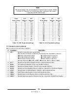
Table 6-4: SW1-3 Setting and Programming Range
Figure 6-2: Remote Voltage Programming Connection
1
14
13
25
10
9
23
22
CURRENT LIMIT
PROGRAMMING
OUTPUT VOLTAGE
PROGRAMMING
J1 connector, rear panel view
Fig.6-2: Remote resistive programming
PROGRAMMING
RESISTOR
PROGRAMMING
RESISTOR
OPTIONAL SETS
LOWER LIMIT
OPTIONAL SETS
LOWER LIMIT
OPTIONAL SETS
UPPER LIMIT
OPTIONAL SETS
UPPER LIMIT
12
8
Содержание GENESYS GEN 2400W Series
Страница 2: ...83 517 000 Rev A THIS PAGE INTENTIONALLY LEFT BLANK ...
Страница 3: ......
Страница 4: ......
Страница 6: ...83 517 000 Rev A THIS PAGE INTENTIONALLY LEFT BLANK ...
Страница 31: ...83 517 000 Rev A 21 2 15 GENESYSTM 2400W POWER SUPPLY OUTLINE DRAWING ...

