Section 13.0 Appendix D: DeviceNet Gateway Option
HGA IOM
130
•
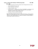
Click on the Module tab of the 1769 SDN scanner Module window.
•
In the platform drop down menu, select MicroLogix.
•
Keep slot as 1.
•
Proceed to the Input tab of the 1769 SDN scanner module window.
•
Note, that the registers 0-65 are read-only.
•
Therefore, the Anybus data is saved in the registers 66-73 each register being 16 bits.
•
Similarly, in the output tab, the first 2 registers are read-only. The 3rd register will say Anybus
Communicator, meaning that the Anybus data is redirected and mapped to that register in the
1769 SDN.
•
Once set, click on “Apply” and then click “OK”.
•
The 1769 DeviceNet Scanner is now also set for proper communication with Anybus
Communicator.
RSLogix
•
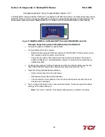
RSLogix is used to program the ML1500 PLC. Once in RSLogix, a new file is created and the
PLC ML1500 revision C is selected in the list of compatible PLCs.
•
The “Who Active” option is used to connect the live PLC to the software.
•
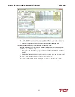
In RSLogix, the IOConfiguration option present on the left panel is selected.
•
A new window will open, from the list of items present on the right panel, select the 1769
DeviceNet Scanner.
•
Once selected, the DeviceNet Scanner should move to spot 1 in the left panel of the window,
given that no other I/O modules are attached to the PLC.
•
Click on the ReadI/O option. The program will try to read the IO profile of the DeviceNet
scanner once found a message box confirming the same will appear.
•
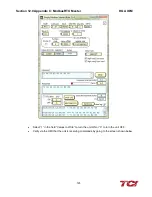
In the IOConfiguration screen click on the Adv. Config option present on the bottom left.
•
In this option, the Input and Output words can be selected for the Scanner. Select 73 Input
words and 3 Output words.
•
The first 65 input words are reserved; the words 66-73 are used to store the HMI data coming
in from the Anybus Gateway. Similarly, the first 2 output words are reserved leaving 1 word for
HMI data.
•
The Input and Output data files present on the left panel of the RSLogix software hold the
DeviceNet Scanner register values.
•
The reserved word definitions can be looked at in the scanner manual, they serve as status
bits. The output bit O: 1.0 is the run bit for the scanner and can be toggled in the output data
file.
•
Once the data files are understood, the PLC is put into run mode and the data from the HMI
can be seen in the IO data files.
•
Based on this information, the below ladder diagram was built to observe the HMI status and
report it though the DeviceNet network on a LED status setup.
Содержание HGA HarmonicGuard Series
Страница 26: ...Section 4 0 Pre installation Planning HGA IOM 19 Figure 3 Altitude and Ambient Temperature Derating ...
Страница 40: ...Section 5 0 Installation Guidelines HGA IOM 33 Figure 11 HGA 480 V Two Unit Parallel Connection Diagram ...
Страница 42: ...Section 5 0 Installation Guidelines HGA IOM 35 Figure 12 HGA 480 V Three Wide Parallel Unit Connection Diagram ...
Страница 47: ...Section 5 0 Installation Guidelines HGA IOM 40 Figure 16 HGA 480 V Main Tie Main Connection Diagram ...
Страница 48: ...Section 5 0 Installation Guidelines HGA IOM 41 Figure 17 Current Transformer Diagram Round ...
Страница 49: ...Section 5 0 Installation Guidelines HGA IOM 42 Figure 18 Current Transformer Diagram Rectangular ...
Страница 76: ...Section 7 0 HMI Introduction HGA IOM 69 HMI Installation Diagram ...
Страница 138: ...Section 13 0 Appendix D DeviceNet Gateway Option HGA IOM 131 Figure 80 Ladder Diagram Observing HMI Status ...


