Section 13.0 Appendix D: DeviceNet Gateway Option
HGA IOM
126
Configuration
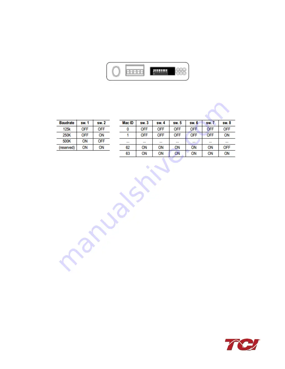
To configure the DeviceNet gateway on the DeviceNet network a node ID needs to be configured
on the DeviceNet. The node address can be assigned by setting the configuration switches on
the Anybus as shown in the image
Figure 77: Anybus Configuration Switches
The values of the switches represent are listed in the table below:
Figure 78: Anybus Switch Values
After a node address has been assigned, the gateway can be connected to the DeviceNet
network by using RSNetworks for DeviceNet devices.
The EDS file for the DeviceNet Communications Gateway is available via TCI technical support
(direct dial: 414-357-4541, email [email protected]) or from the TCI website
(http://www.transcoil.com/Support.htm)
For advanced configuration options, reference the HMS Anybus Communicator Serial DeviceNet
Gateway User Manual available on the HMS website (www.hms.se)
Operation
The Communication Gateway has six LED indicators that show the current status of the Modbus
TCP/IP and sub-network communications. The meanings of the LED indicators are described
below.
Содержание HGA HarmonicGuard Series
Страница 26: ...Section 4 0 Pre installation Planning HGA IOM 19 Figure 3 Altitude and Ambient Temperature Derating ...
Страница 40: ...Section 5 0 Installation Guidelines HGA IOM 33 Figure 11 HGA 480 V Two Unit Parallel Connection Diagram ...
Страница 42: ...Section 5 0 Installation Guidelines HGA IOM 35 Figure 12 HGA 480 V Three Wide Parallel Unit Connection Diagram ...
Страница 47: ...Section 5 0 Installation Guidelines HGA IOM 40 Figure 16 HGA 480 V Main Tie Main Connection Diagram ...
Страница 48: ...Section 5 0 Installation Guidelines HGA IOM 41 Figure 17 Current Transformer Diagram Round ...
Страница 49: ...Section 5 0 Installation Guidelines HGA IOM 42 Figure 18 Current Transformer Diagram Rectangular ...
Страница 76: ...Section 7 0 HMI Introduction HGA IOM 69 HMI Installation Diagram ...
Страница 138: ...Section 13 0 Appendix D DeviceNet Gateway Option HGA IOM 131 Figure 80 Ladder Diagram Observing HMI Status ...


