


Section 12.0 Appendix C: ModbusRTU Master
HGA IOM
120
12.0 Appendix C: ModbusRTU Master
Introduction
The HGA Modbus RTU network communication interface transmits and receives command and
status data from the HGA HMI display to a connected Modbus master over a RS-485 serial link.
ModbusRTU is a simple serial communications protocol originally developed by Modicon for use
with Programmable Logic Controllers (PLCs) in control of industrial devices. ModbusRTU is
commonly supported by most PLCs and is an open, royalty-free communications standard.
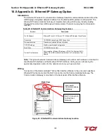
Wiring and Configuration
The HGA implements a ModbusRTU slave device, which can be accessed by a connected
ModbusRTU master that supports two wire RS-485 signal levels. The HGA HMI communication
port used for the Modbus RTU interface is COM3. The COM3 serial connection header is shared
with the COM2 port. The COM2/COM3 port is located on the back of the HMI display.
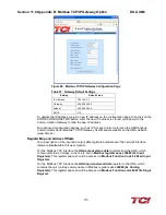
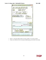
Figure 72: Modbus RTU Connection
The hardware pinout for the HMI COM3 port and the default settings are shown below.
Table 53: HMI COM3 Port Pinout and Default Settings
COM2/3
DB9 Pin
Signal Name
Signal Type
1
no connect
-
2
no connect
-
3
no connect
-
4
D+
RS-485 B (non-inverting)
5
GND
RS-485 SC/G
6
no connect
-
7
no connect
-
8
no connect
-
9
D-
RS-485 A (inverting)
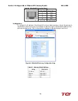
The default protocol settings for the RS-485 ModbusRTU interface on COM3 are show below.
Table 54: RS-485 ModbusRTU interface on COM3 Default Settings
Parameter
Default Value
Units
Baud Rate
19200
bps
Data Bits
8
bits
Stop Bits
1
bits
Parity
Even
-
Slave ID
113
-
The default settings can be modified via the HMI system menu. Please reference
the HMI
Modbus RTU COM Change Instructions
at the end of this document to change the default
protocol settings.
ModbusRTU
Connection
Содержание HGA HarmonicGuard Series
Страница 26: ...Section 4 0 Pre installation Planning HGA IOM 19 Figure 3 Altitude and Ambient Temperature Derating ...
Страница 40: ...Section 5 0 Installation Guidelines HGA IOM 33 Figure 11 HGA 480 V Two Unit Parallel Connection Diagram ...
Страница 42: ...Section 5 0 Installation Guidelines HGA IOM 35 Figure 12 HGA 480 V Three Wide Parallel Unit Connection Diagram ...
Страница 47: ...Section 5 0 Installation Guidelines HGA IOM 40 Figure 16 HGA 480 V Main Tie Main Connection Diagram ...
Страница 48: ...Section 5 0 Installation Guidelines HGA IOM 41 Figure 17 Current Transformer Diagram Round ...
Страница 49: ...Section 5 0 Installation Guidelines HGA IOM 42 Figure 18 Current Transformer Diagram Rectangular ...
Страница 76: ...Section 7 0 HMI Introduction HGA IOM 69 HMI Installation Diagram ...
Страница 138: ...Section 13 0 Appendix D DeviceNet Gateway Option HGA IOM 131 Figure 80 Ladder Diagram Observing HMI Status ...