Section 11.0 Appendix B: Modbus TCP/IP Gateway Option
HGA IOM
119
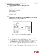
Write To HMI
•
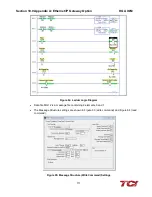
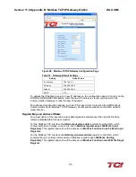
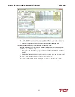
Reference figure above and click the write command in the Simply Modbus main window.
•
Select the first register value as “0”
(1)
.
•
Select the data type as 16-bit INT
(2)
.
•
Set the minus offset to “0”
(3).
•
Write the value as “1” in register number “0”
(4)
and hit SEND
(5)
. The unit will begin to run if
the network run command enable is enabled. If the network run command enable is
off/disabled, the network run command will be ignored.
•
Sending “0” in the same command will stop the unit.
•
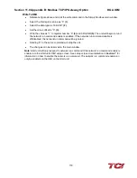
The changes can be observed in the main window.
Note
: HGA unit will only respond to network run command if the network run command enable is
enabled via the HGA unit’s HMI setup screen. See setup screen documentation in
Section 7
for
information on how to enable the network run command. The network run command enable can
only be enabled via the HMI on the HGA unit.
Содержание HGA HarmonicGuard Series
Страница 26: ...Section 4 0 Pre installation Planning HGA IOM 19 Figure 3 Altitude and Ambient Temperature Derating ...
Страница 40: ...Section 5 0 Installation Guidelines HGA IOM 33 Figure 11 HGA 480 V Two Unit Parallel Connection Diagram ...
Страница 42: ...Section 5 0 Installation Guidelines HGA IOM 35 Figure 12 HGA 480 V Three Wide Parallel Unit Connection Diagram ...
Страница 47: ...Section 5 0 Installation Guidelines HGA IOM 40 Figure 16 HGA 480 V Main Tie Main Connection Diagram ...
Страница 48: ...Section 5 0 Installation Guidelines HGA IOM 41 Figure 17 Current Transformer Diagram Round ...
Страница 49: ...Section 5 0 Installation Guidelines HGA IOM 42 Figure 18 Current Transformer Diagram Rectangular ...
Страница 76: ...Section 7 0 HMI Introduction HGA IOM 69 HMI Installation Diagram ...
Страница 138: ...Section 13 0 Appendix D DeviceNet Gateway Option HGA IOM 131 Figure 80 Ladder Diagram Observing HMI Status ...


