


Section 11.0 Appendix B: Modbus TCP/IP Gateway Option
HGA IOM
117
Setup
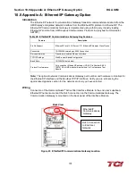
•
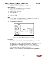
Connect the RJ45 cable to the Ethernet Port on the Anybus gateway from a router (LAN).
•
Connect the PC to the router (LAN) via RJ45 Ethernet cable.
•
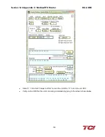
The network setup is displayed below.
Figure 69: Network Setup with PC Example
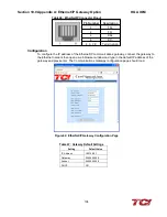
Programming
•
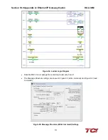
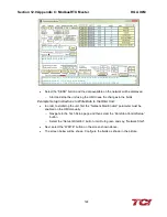
Once all connections are set, the Modbus TCP master is ready for communication.
•
In the example, the Modbus TCP master is “Simply Modbus”
Figure 70: Simply Modbus Screen
1
2
3
4
5
7
8
9
10
Содержание HGA HarmonicGuard Series
Страница 26: ...Section 4 0 Pre installation Planning HGA IOM 19 Figure 3 Altitude and Ambient Temperature Derating ...
Страница 40: ...Section 5 0 Installation Guidelines HGA IOM 33 Figure 11 HGA 480 V Two Unit Parallel Connection Diagram ...
Страница 42: ...Section 5 0 Installation Guidelines HGA IOM 35 Figure 12 HGA 480 V Three Wide Parallel Unit Connection Diagram ...
Страница 47: ...Section 5 0 Installation Guidelines HGA IOM 40 Figure 16 HGA 480 V Main Tie Main Connection Diagram ...
Страница 48: ...Section 5 0 Installation Guidelines HGA IOM 41 Figure 17 Current Transformer Diagram Round ...
Страница 49: ...Section 5 0 Installation Guidelines HGA IOM 42 Figure 18 Current Transformer Diagram Rectangular ...
Страница 76: ...Section 7 0 HMI Introduction HGA IOM 69 HMI Installation Diagram ...
Страница 138: ...Section 13 0 Appendix D DeviceNet Gateway Option HGA IOM 131 Figure 80 Ladder Diagram Observing HMI Status ...