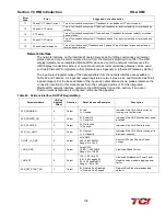
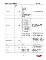
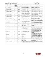


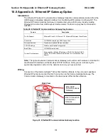


Section 11.0 Appendix B: Modbus TCP/IP Gateway Option
HGA IOM
114
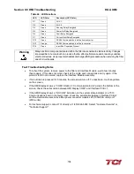
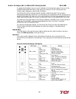
Table 50: Modbus TCP/IP Connector Pinout
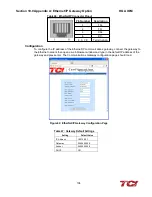
Configuration
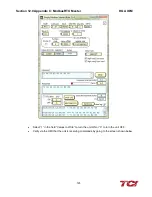
To configure the IP address of the Modbus TCP/IP communications gateway, there are two
options. The preferred method is to use the IPConfig tool provided by HMS. This can be
downloaded for free from their website www.anybus.com.
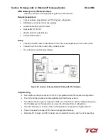
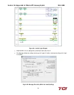
For this option, first connect a computer to the same network that the Anybus module is
connected. Next, open the IPConfig tool. Select “Scan” and the device should be present on the
screen with the default IP address shown below.
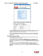
To change this to a desired IP address, simply select it, right click and go to “Configuration”. Here
the new address and network information can be entered.
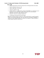
The gateway can also be connected to the Ethernet network and then open a web browser
window and type in the default IP address of the gateway and press enter. The Communications
Gateway configuration page should load.
Pin Number Description
1
TD+
2
TD-
3
RD+
6
RD-
4, 5, 7, 8
Termination
Содержание HGA HarmonicGuard Series
Страница 26: ...Section 4 0 Pre installation Planning HGA IOM 19 Figure 3 Altitude and Ambient Temperature Derating ...
Страница 40: ...Section 5 0 Installation Guidelines HGA IOM 33 Figure 11 HGA 480 V Two Unit Parallel Connection Diagram ...
Страница 42: ...Section 5 0 Installation Guidelines HGA IOM 35 Figure 12 HGA 480 V Three Wide Parallel Unit Connection Diagram ...
Страница 47: ...Section 5 0 Installation Guidelines HGA IOM 40 Figure 16 HGA 480 V Main Tie Main Connection Diagram ...
Страница 48: ...Section 5 0 Installation Guidelines HGA IOM 41 Figure 17 Current Transformer Diagram Round ...
Страница 49: ...Section 5 0 Installation Guidelines HGA IOM 42 Figure 18 Current Transformer Diagram Rectangular ...
Страница 76: ...Section 7 0 HMI Introduction HGA IOM 69 HMI Installation Diagram ...
Страница 138: ...Section 13 0 Appendix D DeviceNet Gateway Option HGA IOM 131 Figure 80 Ladder Diagram Observing HMI Status ...