Section 11.0 Appendix B: Modbus TCP/IP Gateway Option
HGA IOM
113
11.0 Appendix B: Modbus TCP/IP Gateway Option
Introduction
The Modbus TCP/IP network Communications Gateway translates command/status data to/from
the HMI Display’s integrated network interface from the Modbus RTU protocol to Modbus TCP/IP.
Modbus TCP/IP (also Modbus-TCP) is simply the Modbus-RTU protocol with a TCP interface that
runs on Ethernet. The Modbus TCP/IP Communications Gateway is implemented using a third
party, industry leading Modbus TCP/IP solution from HMS Anybus Communicator Product Line
(Anybus Communicator AB7007).
Table 49: Modbus TCP/IP Communications Gateway Key Features
Feature
Description
Profile Support
Modbus/TCP class 0, class 1 and partially class 2 slave functionality
Connection
10/100 MBit twisted pair RJ45 Connection
Galvanic Isolation
Transformer isolated Ethernet interface
TCP/IP Settings
Web Browser Based Configuration
Baud Rate
10/100 MBit auto detect
Protocol Conformance
Fully compliant Modbus TCP/IP gateway See HMS website
(www.hms.se) for Conformance Test Results.
Note:
The optional network Communications Gateway part number and hardware is identical for
the Ethernet/IP interface and the Modbus TCP/IP interface. Verify you are referencing the
appropriate Appendix section for the network protocol you have selected.
Wiring
Connection of the HarmonicGuard
®
Active filter Interface Module to the end user’s upstream
Modbus TCP/IP network occurs at the RJ45 connection on the Communications Gateway. The
Communication Gateway is mounted on the back panel of the Interface Module.
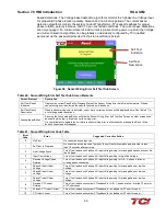
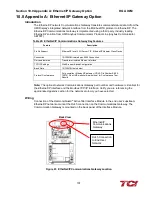
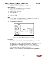
Figure 67: Modbus TCP/IP Communications Gateway Location
Ethernet/IP and
Modbus TCP
Communications
Gateway
RJ45 Connection
to End User
Network
Back View
Содержание HGA HarmonicGuard Series
Страница 26: ...Section 4 0 Pre installation Planning HGA IOM 19 Figure 3 Altitude and Ambient Temperature Derating ...
Страница 40: ...Section 5 0 Installation Guidelines HGA IOM 33 Figure 11 HGA 480 V Two Unit Parallel Connection Diagram ...
Страница 42: ...Section 5 0 Installation Guidelines HGA IOM 35 Figure 12 HGA 480 V Three Wide Parallel Unit Connection Diagram ...
Страница 47: ...Section 5 0 Installation Guidelines HGA IOM 40 Figure 16 HGA 480 V Main Tie Main Connection Diagram ...
Страница 48: ...Section 5 0 Installation Guidelines HGA IOM 41 Figure 17 Current Transformer Diagram Round ...
Страница 49: ...Section 5 0 Installation Guidelines HGA IOM 42 Figure 18 Current Transformer Diagram Rectangular ...
Страница 76: ...Section 7 0 HMI Introduction HGA IOM 69 HMI Installation Diagram ...
Страница 138: ...Section 13 0 Appendix D DeviceNet Gateway Option HGA IOM 131 Figure 80 Ladder Diagram Observing HMI Status ...

