31/ 42
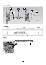
Left crankcase cover installation
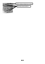
Install the positioning pins in place, and then align the positioning pins to install the left crankcase cover in place. After
pre-tightening the bolts of the left crankcase cover evenly diagonally, tighten them with a fixed torque at a torque of 12 ± 1.5
N.m.
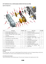
Continuously variable clutch sub-assembly
Assembly
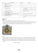
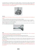
Place the special CVT limit fixture according to the position shown in the figure to limit the driving and driven wheels so that the
driving and driven wheels cannot rotate freely.
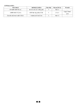
Use a torque wrench (or air batch) and a 17# sleeve
Assembly the M12×1.25 hexagon flange surface 10-grade nuts
counterclockwise
, and remove the φ12.2×φ29×2.5 gasket, 12×24×2.6 butterfly shaped spring washer and φ12.8×φ25×16.7
driven wheel bushing, then remove the positioning fixture for the driving and driven wheels, remove the ZT1P52MI main fixed
plate from the crankshaft, and remove the driven wheel clutch jacket from the drive shaft. Pinch the middle part of the V-shaped
driving belt, and remove the belt and driven wheel sub-assembly together. Pinch the main sliding wheel subassembly and the
ramp plate inside, and remove it together with the driving wheel bushing.
Inspection
Check whether the centrifugal roller is worn and out of round, if it is out of round and deformed, it needs to be replaced.
Check the v -shaped transmission belt for cracks, broken wires, tooth loss, etc., and replace it if it occurs.
Check whether the inner circular surface of the driven wheel clutch casing and the driven wheel clutch shoe are abnormally worn
or damaged, and if they are abnormally worn or damaged, they need to be replaced. (note
: it is not recommended to grind the
clutch shoes, which will increase the wear of the inner ring of the clutch casing and the clutch shoes, and may also cause
riding vibration.)
Install
1. Install the positioning pin in place, and then put the ZT1P58MJ left crankcase cover gasket.
2. Turn over the main sliding wheel subassembly with the centrifugal roller, buffer slider and slope plate installed, and then put
the driving wheel shaft into the inner hole of the main sliding wheel subassembly. Then pinch the sliding disc and the ramp plate
with one hand (to prevent the centrifugal roller from falling after being disassembled), and hold the exposed driving wheel
6005 bearing


