background image

6-6  

OPERATING PROCEDURES

Models C709 & C717

Operating Procedures 

7.

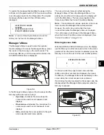
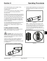
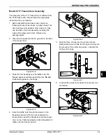
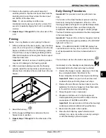
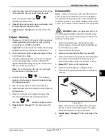
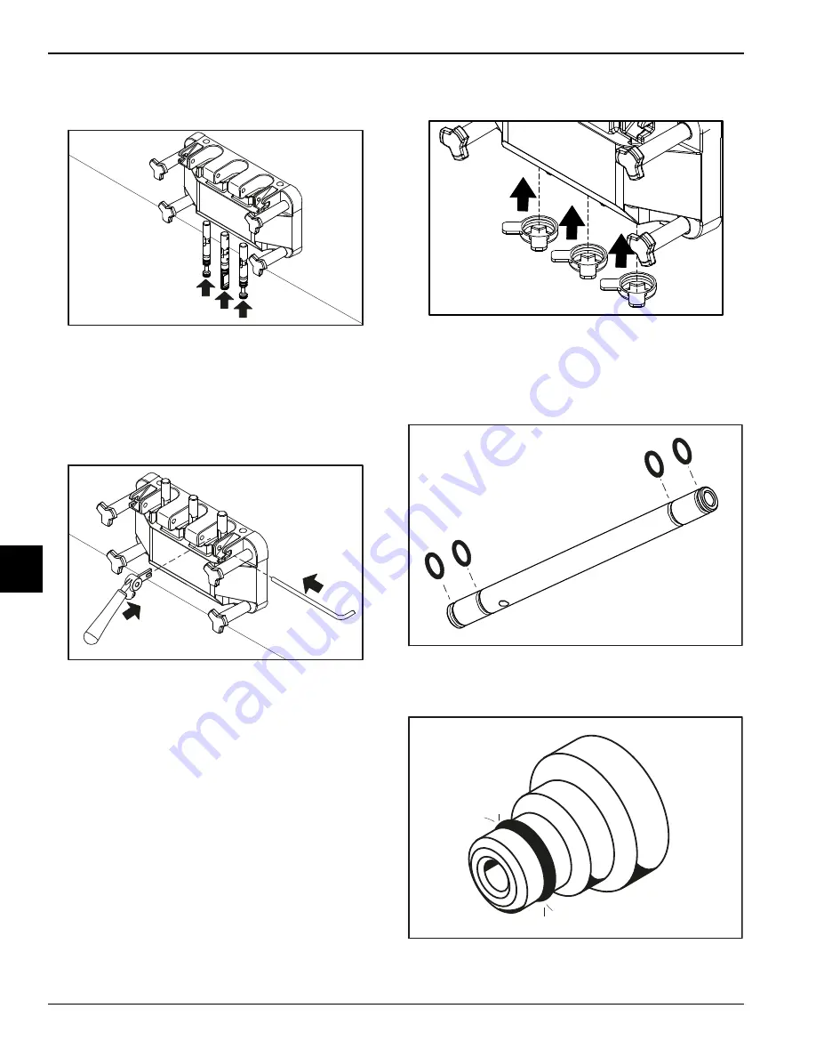
Insert the draw valves from the bottom until the slot in 

each draw valve comes into view. 

Figure 6-23

8.

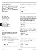
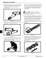
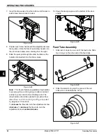
Position each draw handle with the adjustment screw 

facing down. Slide the fork of each draw handle into 

the slot of each draw valve, starting from the right.

9.

Slide the pivot pin through the draw handles as the 

handles are inserted into the draw valves.

Figure 6-24

Note:

This freezer features adjustable draw handles 

to provide portion control, giving a better consistent 

quality to your product and controlling costs. The 

draw handles should be adjusted to provide a flow 

rate of 5 

oz. 

to 7-1/2 oz. (142 g to 213 g) of product 

by weight per 10 seconds.

To 

increase

 the flow rate, turn the adjustment screw 

clockwise

. To 

decrease

 the flow rate, turn the 

adjustment screw 

counterclockwise

.

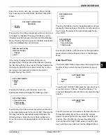
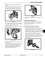
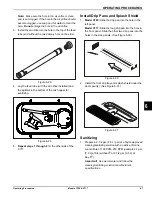
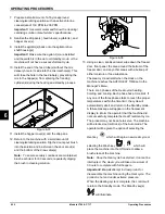
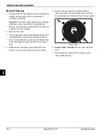
10. Snap the design caps over the bottom of the door 

spouts.

Figure 6-25

Feed Tube Assembly

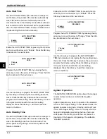
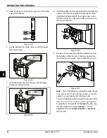
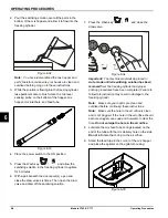
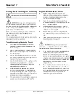
1. Slide two O-rings on one end of the feed tube. Slide 

two O-rings on the other end of the feed tube.

Figure 6-26

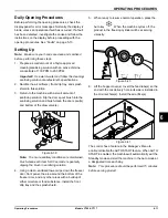
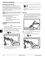
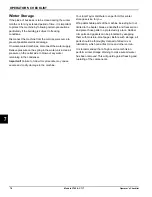
2. Slide the small O-ring into the groove of the air 

orifice. Do not lubricate the O-ring.

Figure 6-27

101534

101535

101544

12317

12077

Содержание C709

Страница 1: ...OPERATOR S MANUAL Model C709 and C717 Blade Style Beater Heat Treatment Soft Serve Freezers Original Operating Instructions 083129 M 9 30 14 Original Publication Updated 11 8 2019...

Страница 2: ...__ Cycle__________ Phase__________________________________ Maximum Fuse Size ______________________________________________________ A Minimum Wire Ampacity ____________________________________________...

Страница 3: ...Section 3 Safety Section 4 Operator Parts Identification Model C709 4 1 Model C717 4 3 Model C709 Single Spout Door and Beater Assembly 4 5 Model C717 Three Spout Door and Beater Assembly 4 6 Feed Tu...

Страница 4: ...Setting Up 6 11 Manual Brush Cleaning 6 12 Draining Product from the Freezing Cylinder 6 12 Rinsing 6 12 Hopper Cleaning 6 13 Disassembly 6 13 Brush Cleaning 6 14 Section 7 Operator s Checklist During...

Страница 5: ...ine must be disconnected prior to performing any installation maintenance or repairs Failure to follow this instruction may result in personal injury or death from electrical shock or hazardous moving...

Страница 6: ...ough the automatic water valve second through the condenser and third through the outlet fitting to an open trap drain IMPORTANT A backflow prevention device is required on the incoming water connecti...

Страница 7: ...main control box located behind the service panel It is recommended that beater rotation adjustment be performed by an authorized Taylor service technician Refrigerant CAUTION This machine contains fl...

Страница 8: ...1 4 TO THE INSTALLER Models C709 C717 To the Installer 1 Notes...

Страница 9: ...tor Note Your Taylor warranty is valid only if parts are authorized Taylor parts purchased from a local authorized Taylor distributor and only if all required service work is provided by an authorized...

Страница 10: ...status of an alternate refrigerant as it relates to your compressor warranty call Taylor or your local authorized Taylor distributor Be prepared to provide the model serial number of the machine in qu...

Страница 11: ...ion supervision or instruction concerning the use of the machine by a person responsible for their safety is required Children should be supervised to ensure that they do not play with the machine WAR...

Страница 12: ...nd sanitizing schedules are governed by your federal state or local regulatory agencies and must be followed accordingly Please refer to the cleaning section of this manual for the proper procedure to...

Страница 13: ...Section 4 4 1 Models C709 C717 Operator Parts Identification 4 Model C709 Figure 4 1 4 2 6 5 3 5 1 17 13 12 7 7 8 9 10 11 10 14 16 15 Operator Parts Identification...

Страница 14: ...ng Hopper CVR 043934 4 Kit A Cover Hopper X65368 5 Blade A Agitator X56591 6 Orifice 022465 100 7 O ring 643 OD x 077W 018572 8 Tube A Feed SS 5 32 Hole X29429 2 9 Panel Rear 083017 SP1 Item Descripti...

Страница 15: ...OPERATOR PARTS IDENTIFICATION 4 3 Models C709 C717 Operator Parts Identification 4 Model C717 Figure 4 2 5 7 2 20 9 22 3 4 6 7 8 12 8 13 14 16 15 19 17 18 3 1 10 11...

Страница 16: ...1 2 Long 059736 8 Screw 1 4 20 x 3 8 RHM SS 011694 9 Panel A Front Upper X59836 10 Stud Nose Cone 055987 11 Panel A Front Middle X63879 12 Caster 4 SWV 3 4 10 STM 044106 Item Description Part No 13 P...

Страница 17: ...50 015872 3 Screw Adjustment 5 16 24 056332 SP 4 Valve A Draw X55820 5 O ring 7 8 OD x 103W 014402 6 Kit A Beater Front Shoes Bearing X50350 7 Beater A 3 4QT 1 Pin X46231 8 Shaft Beater 056078 9 Seal...

Страница 18: ...ring 1 4 OD x 070W 50 015872 4 Screw Adjustment 5 16 24 056332 SP 5 Kit A Beater Front Shoes Bearing X50350 6 Beater A 3 4QT 1 Pin X46231 7 Shaft Beater 032564 8 Seal Drive Shaft 032560 9 Blade Scrape...

Страница 19: ...C717 Operator Parts Identification 4 Feed Tube Assembly Figure 4 5 3 4 3 1 2 Item Description Part No 1 Orifice 022465 100 2 O ring 3 8 OD x 070W 016137 Item Description Part No 3 O ring 643 OD x 077...

Страница 20: ...rt no 055492 100 2 oz packs or Kay 5 part no 041082 200 packs Not Shown Apply the appropriate Taylor approved food safe lubricant HP 3 4 1 2 Item Description Part No 1 Pail 10 QT 013163 2 Tool O ring...

Страница 21: ...ts Identification 4 Brushes Figure 4 7 1 2 3 4 5 Item Description Part No 1 Brush Rear BRG 1 D x 2 L 013071 2 Brush Double Ended 013072 3 Brush Draw Valve 1 OD x 2 013073 Item Description Part No 4 Br...

Страница 22: ...4 10 OPERATOR PARTS IDENTIFICATION Models C709 C717 Operator Parts Identification 4 Notes...

Страница 23: ...5 1 Item Description 1 Power Switch 2 Vacuum Fluorescent Display 3 Keypads 4 Mix Out Indicator 5 Standby Key 6 Mix Low Indicator 7 Select Key 8 Menu Key 9 Brush Clean Counter 10 Arrow Keys 11 Topping...

Страница 24: ...been almost completely exhausted and has an insufficient supply of mix to operate the machine At this time the Auto mode is locked out and the machine will be placed in the Standby mode To restart the...

Страница 25: ...the end with the mix delivery hole in its side is installed in the mix inlet hole Install the air orifice See Feed Tube Assembly on page 5 4 Reset Mechanism The C709 machine s RESET button is in the s...

Страница 26: ...hole in its side Place that end of the tube into the mix inlet hole This will prevent mix from entering the freezing cylinder Figure 5 5 Important When the feed tube is in the standby position make s...

Страница 27: ...ata in the machine s memory System data includes settings that change frequently such as the machine mode e g Auto Wash lockout status serving counters and fault codes While system data is being check...

Страница 28: ...ontrol panel press keys become operative The fluorescent display will be either blank or indicate that the machine has been cleaned International Models Only Some international models will continuousl...

Страница 29: ...und in this Operator s Manual Failure to follow these guidelines will cause the control to lock the machine out of the Auto mode If the Heat Treatment cycle fails the screen will display a failure mes...

Страница 30: ...Treatment cycle A soft lock can also occur anytime during operation when the hopper or freezing cylinder temperature rises above 59 F 15 C the temperature rises and remains above 45 F 7 C for more tha...

Страница 31: ...ing the Manager s Menu While in the Manager s Menu if no activity occurs within a 2 minute period the display will exit to the Main Menu There is one exception to this timeout and that is the Current...

Страница 32: ...he SEL key to advance to the next screen Press the Up arrow key to move the arrow to Yes and press the SEL key The servings counter will reset to zero and exit back to the Manager s Menu Set Clock The...

Страница 33: ...ate month for the end of DST Pressing the SEL key next to the appropriate month will display the following screen Press the Up or Down arrow key to move the arrow to the appropriate week for the end o...

Страница 34: ...s power saving during slow sales By default this feature is disabled Enable the AUTO STANDBY TIME by pressing the Up arrow key to move the arrow up to Enable Press the SEL key to advance to the next s...

Страница 35: ...will appear on the screen after this variable message appears BEATER OVERLOAD Place the power switch in the OFF position Wait 5 minutes for the machine to cool Press the beater RESET button firmly Pla...

Страница 36: ...xceeded the brush clean cycle setting POWER SWITCH OFF The power switch was turned off during the Heat cycle POWER FAIL IN H C A power failure occurred during the Heat Treatment cycle MIX LOW FAILURE...

Страница 37: ...the hopper h and barrel b temperature was above 150 F 65 6 C COOL Total time the hopper h and barrel b temperature was above 41 F 5 C during the cool phase PEAK Highest temperature reading for the hop...

Страница 38: ...enable disable the WIFI gateway if the machine has the optional WIFI equipment Press the Up or Down arrow key to move the arrow to the appropriate selection Pressing the SEL key with the arrow by the...

Страница 39: ...here Freezing Cylinder Assembly Note When lubricating parts use an approved food grade lubricant example Taylor Lube HP WARNING Make sure the power switch is in the OFF position Failure to follow this...

Страница 40: ...en it was installed onto the rear shell bearing WARNING Use extreme caution when handling the beater assembly The scraper blades are very sharp and may cause injury 6 Before installing the beater asse...

Страница 41: ...beater is properly seated When in position the beater will not protrude beyond the front of the freezing cylinder See Figure 6 11 Figure 6 11 12 Repeat steps 1 through 11 for the other side of the C7...

Страница 42: ...s secured Figure 6 16 7 Position the draw handle with the adjustment screw facing down Slide the fork of the draw handle into the slot of the draw valve Secure with the pivot pin Figure 6 17 Note The...

Страница 43: ...he flanged edges should be against the door Do not lubricate the gaskets or bearings Figure 6 19 4 Insert the baffle rods through the beaters in the freezing cylinders With the door seated on the free...

Страница 44: ...ovide portion control giving a better consistent quality to your product and controlling costs The draw handles should be adjusted to provide a flow rate of 5 oz to 7 1 2 oz 142 g to 213 g of product...

Страница 45: ...s 1 through 4 for the other side of the C717 Install Drip Pans and Splash Shield 1 Model C709 Slide the drip pan into the hole in the left panel Model C717 Slide the long drip pan into the hole in the...

Страница 46: ...ix times Then open the draw valve and draw off the sanitizing solution 7 Press the Wash key and close the draw valve Figure 6 34 Important The machine must not be placed in Auto mode until all sanitiz...

Страница 47: ...destroy bacteria by raising the temperature of the mix in the freezing cylinder and hopper to a specified temperature for a specified period of time and then bringing the temperature back down low en...

Страница 48: ...ion Figure 6 38 13 Using a clean sanitized towel wipe down the freezer door front panel the area around the bottom of the freezer door and any other areas with a buildup of either moisture or food sub...

Страница 49: ...on and brush clean the door spout s and bottom of the draw valve s Figure 6 39 Note To ensure sanitary conditions are maintained brush clean each item for 60 seconds repeatedly dipping the brush in sa...

Страница 50: ...ddle and feed tube Take these parts to the sink for cleaning 3 With a pail beneath the door spout s press the Wash key and open the draw valve Figure 6 42 Drain the product from the freezing cylinder...

Страница 51: ...nd draw off all the solution 7 Once the cleaning solution stops flowing from the door spout close the draw valve and press the Wash key canceling the Wash mode 8 Repeat steps 1 through 7 for the other...

Страница 52: ...oughly brush clean all disassembled parts in the cleaning solution making sure all lubricant and mix film is removed Make sure to brush all surfaces and holes especially the draw valve hole in the fre...

Страница 53: ...ng or sanitizing The temperature of the mix in the mix hopper and walk in cooler should be below 40 F 4 4 C Regular Maintenance Checks Replace scraper blades that are nicked or damaged Before installi...

Страница 54: ...r remaining in the condenser Important Failure to follow this procedure may cause severe and costly damage to the machine Your local Taylor distributor can perform this winter storage service for you...

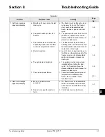
Страница 55: ...The freezer must now be disassembled and brush cleaned or placed in a Heat cycle 5 9 d Mix Out condition d Level of mix in hopper must be up to the fill line on the agitator paddle The freezer must no...

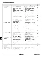
Страница 56: ...ines b Allow for adequate airflow across the condenser 1 2 c Worn scraper blades c Replace regularly 9 1 d Dirty condenser A C d Clean monthly 7 1 e Mix is out of date e Use only fresh mix f Loss of w...

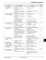
Страница 57: ...ont bearing and beater shoes 6 3 b Scraper blades are damaged b Replace scraper blades 6 3 c Machine was placed in Auto mode before all sanitizing solution was removed from freezing cylinder c Place m...

Страница 58: ...8 4 TROUBLESHOOTING GUIDE Models C709 C717 Troubleshooting Guide 8 Notes...

Страница 59: ...ring X Draw Valve O ring X Mix Feed Tube O ring X Air Orifice O ring X White Bristle Brush 3 x 7 White Bristle Brush 1 x 2 Inspect and replace if necessary Minimum White Bristle Brush 1 x 2 Inspect an...

Страница 60: ...9 2 PARTS REPLACEMENT SCHEDULE Models C709 C717 Parts Replacement Schedule 9 Notes...

Страница 61: ...ED WARRANTY CONDITIONS 1 If the date of original installation of the Product cannot be verified then the limited warranty period begins ninety 90 days from the date of Product manufacture as indicated...

Страница 62: ...irs due to theft vandalism wind rain flood high water water lightning earthquake or any other natural disaster fire corrosive environments insect or rodent infestation or other casualty accident or co...

Страница 63: ...AL OR INCIDENTAL DAMAGES INCLUDING CLAIMS FOR LOST SALES LOST PROFITS PRODUCT LOSS PROPERTY DAMAGES OR SERVICE EXPENSES ARE EXPRESSLY EXCLUDED THE EXPRESS WARRANTIES MADE IN THIS LIMITED WARRANTY MAY...

Страница 64: ...10 4 LIMITED WARRANTY ON EQUIPMENT Models C709 C717 Limited Warranty on Equipment 10 Notes...

Страница 65: ...ified proof of purchase may be required at time of service 2 This limited warranty is valid only if the Part is installed and all required service work in connection with the Part is performed by an a...

Страница 66: ...g warranty service work promptly upon arrival 9 Failure damage or repairs due to faulty installation misapplication abuse no or improper servicing unauthorized alteration or improper operation or use...

Страница 67: ...R INCIDENTAL DAMAGES INCLUDING CLAIMS FOR LOST SALES LOST PROFITS PRODUCT LOSS PROPERTY DAMAGES OR SERVICE EXPENSES ARE EXPRESSLY EXCLUDED THE EXPRESS WARRANTIES MADE IN THIS LIMITED WARRANTY MAY NOT...

Страница 68: ...11 4 LIMITED WARRANTY ON PARTS Models C709 C717 Limited Warranty on Parts 11 Notes...

Отзывы: