


1-2
TO THE INSTALLER
Models C709 & C717
To the Installer
1
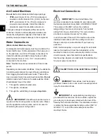
Air-Cooled Machines
Do not
obstruct air intake and discharge openings:
•
C709—
A minimum of 6 in. (152 mm) airspace is
required on both sides and 0 in. (0 mm) on the rear.
•
C717—
A minimum of 3 in. (76 mm) airspace is
required around all sides. Install the deflector
provided to prevent recirculation of warm air.
This space allows for adequate airflow across the
condenser. Failure to allow adequate clearance can
reduce the refrigeration capacity of the freezer and
possibly cause permanent damage to the compressor.
Water Connections
(Water-Cooled Machines Only)
An adequate cold water supply must be provided with a
hand shutoff valve. On the underside of the base pan or
on the right side, two 3/8 in IPS water connections for
inlet and outlet are provided for easy hookup. Inside
diameter water lines of 1/2 in. (12.7 mm) should be
connected to the machine.
Note:
Flexible lines are recommended, if local codes
permit.
Depending on local water conditions, it may be advisable
to install a water strainer to prevent foreign substances
from clogging the automatic water valve. There will be
only one water
in
and one water
out
connection.
Do not
install a hand shutoff valve on the water
out
line. Water
should always flow in this order:
1.
Through the automatic water valve
2.
Through the condenser
3.
Through the outlet fitting to an
open trap drain
IMPORTANT!
A backflow prevention device is
required on the incoming water connection side. Please
see the applicable national, state, and local codes for
determining the proper configuration.
Electrical Connections
IMPORTANT!
In the United States, this
machine is intended to be installed in accordance with
the National Electrical Code (NEC), ANSI/NFPA 701987.
The purpose of the NEC code is the practical
safeguarding of persons and property from hazards
arising from the use of electricity. This code contains
provisions considered necessary for safety.
In all other areas of the world, the machine should be
installed in accordance with the existing local codes.
Please contact your local authorities if you have any
questions.
Each machine requires one power supply for each data
label on the machine. Check the data label(s) on the
machine for branch circuit overcurrent protection or fuse,
circuit ampacity, and other electrical specifications.
See the wiring diagram provided inside the electrical box
for proper power connections.
WARNING!
This machine must be properly
grounded. Failure to do so can result in severe personal
injury from electrical shock.
IMPORTANT!
An equipotential grounding lug is
provided with this machine. Some countries require the
grounding lug to be properly attached to the rear of the
frame by the authorized installer. The installation location
is marked by the equipotential bonding symbol (5021 of
IEC 60417-1) on both the removable panel and the
machine's frame.
FOLLOW YOUR LOCAL ELECTRICAL CODES.
Содержание C709
Страница 8: ...1 4 TO THE INSTALLER Models C709 C717 To the Installer 1 Notes...
Страница 36: ...5 16 USER INTERFACE Models C709 C717 User Interface 5 Notes...
Страница 50: ...6 14 OPERATING PROCEDURES Models C709 C717 Operating Procedures 6 Notes...
Страница 56: ...8 4 TROUBLESHOOTING GUIDE Models C709 C717 Troubleshooting Guide 8 Notes...
Страница 58: ...9 2 PARTS REPLACEMENT SCHEDULE Models C709 C717 Parts Replacement Schedule 9 Notes...
Страница 62: ...10 4 LIMITED WARRANTY ON EQUIPMENT Models C709 C717 Limited Warranty on Equipment 10 Notes...
Страница 66: ...11 4 LIMITED WARRANTY ON PARTS Models C709 C717 Limited Warranty on Parts 11 Notes...