Transaxle
Page 51
MB-210-13
B-200 & B-210 Models
REAR HUB, ROTOR & BEARINGS
Note: The axle hub bolt has a special thread
locking compound applied to the threads. If
this bolt is removed, it must be replaced.
Note: If replacing the bearing, the axle shaft must
be removed from the housing. Refer to Axle
Shaft procedure for information on removing
and installing the axle shaft.
Note: This procedure refers to other procedures
that can be found in this section or other
sections of this manual.
1: Raise the wheel off of the ground.
2: Release the park brake.
3: Remove the tire/wheel assembly.
4: Remove the axle hub bolt and washer and
remove the hub from the axle.
5: Remove the outer brake pad.
6: Remove the rotor.
7: Install in reverse order.
•
Thoroughly clean the threads in the axle shaft.
•
Lightly grease the hub splines.
•
Refer to Brakes section for information
regarding installing the brake pads.
•
Using a new bolt, torque the axle hub bolt to
the specification listed in the table at the end of
this section.
•
Refer to Tires and Wheels section for
information regarding installing the tire/wheel
assembly.
8: Set the park brake.
9: Lower the wheel to the ground and test drive.
This section is one section of a complete service
manual. Before starting any procedure, read all
warnings and instructions that are located in the
Service Guidelines chapter.
WARNING
The axle retaining plate bolts have a pre-applied
thread locking compound. They are intended for one
time use only. If removed they must be replaced.
Reusing the original bolts could cause loss of brakes
resulting in severe bodily injury and/or property
damage.
WARNING
MOTOR, REMOVE
Note: Some applications may require removing
the drive assembly from the vehicle to
remove the motor. Refer to Removing and
Installing the Drive Assembly for information
on removing the drive assembly.
1: Remove the wires from the motor.
2: Remove the motor support bracket U-bolt (only
used on larger motors).
3: Remove the motor mounting bolts and slide the
motor off of the input shaft.
4: Inspect the input shaft O-ring and replace as
needed.
5: Install the motor in reverse order.
6: Apply a light coating of moly paste grease
part number 94-421-34 to the splines on the
transmission input shaft only.
7: Make sure that the motor coupler O-ring is
properly installed on the transmission input shaft.
8: Refer to the torque table in the motor section for
tightening the motor terminals.
9: Reconnect the batteries and test drive.
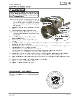
Transmission input shaft
This section is one section of a complete service
manual. Before starting any procedure, read all
warnings and instructions that are located in the
Service Guidelines chapter.
WARNING
The hub bolts have a pre-applied thread locking
compound. They are intended for one time use only. If
removed they must be replaced. Reusing the original
bolts could result in a wheel separating from the axle
and loss of brakes resulting in severe bodily injury
and/or property damage.
WARNING
Содержание B0-200-00
Страница 6: ......
Страница 12: ...Page 12 MB 210 13 Introduction B 200 B 210 Models Notes...
Страница 21: ...Table of Contents Special Tool List Special Tool List Controller Programming 22 Troubleshooting Guide 24...
Страница 28: ...Lubrication Page 28 B 200 B 210 Models MB 210 13 Notes...
Страница 53: ...Transaxle Page 53 MB 210 13 B 200 B 210 Models...
Страница 62: ...Drive Axle Page 62 B 200 B 210 Models MB 210 13 Notes...
Страница 71: ...Steering Page 71 MB 210 13 B 200 B 210 Models Exploded View of Steering Gear...
Страница 81: ...Brakes Page 81 MB 210 13 B 200 B 210 Models...
Страница 118: ...Tires Wheels Page 118 B 200 B 210 Models MB 210 13 Notes...
Страница 130: ...Replacement Parts Page 130 MB 210 13 B 200 B 210 Models AXLE ASSEMBLY FRONT...
Страница 134: ...Replacement Parts Page 134 MB 210 13 B 200 B 210 Models TRANSAXLE ASSEMBLY B 200...
Страница 136: ...Replacement Parts Page 136 MB 210 13 B 200 B 210 Models TRANSAXLE ASSEMBLY B 210 REAR GT...
Страница 140: ...Replacement Parts Page 140 MB 210 13 B 200 B 210 Models BATTERY...
Страница 142: ...Replacement Parts Page 142 MB 210 13 B 200 B 210 Models BRAKES BRAKE LINES...
Страница 144: ...Replacement Parts Page 144 MB 210 13 B 200 B 210 Models BRAKES MASTER CYLINDER LINKAGE...
Страница 148: ...Replacement Parts Page 148 MB 210 13 B 200 B 210 Models BRAKES B 200 REAR AXLE...
Страница 150: ...Replacement Parts Page 150 MB 210 13 B 200 B 210 Models BRAKES B 200 PARK BRAKE...
Страница 152: ...Replacement Parts Page 152 MB 210 13 B 200 B 210 Models BRAKES B 210 PARK BRAKE...
Страница 159: ...Replacement Parts Page 159 Not available at time of printing MB 210 13 B 200 B 210 Models...
Страница 160: ...Replacement Parts Page 160 MB 210 13 B 200 B 210 Models DECALS...
Страница 162: ...Replacement Parts Page 162 MB 210 13 B 200 B 210 Models ELECTRICAL MISCELLANEOUS...
Страница 166: ...Replacement Parts Page 166 MB 210 13 B 200 B 210 Models FRAME DOORS...
Страница 170: ...Replacement Parts Page 170 MB 210 13 B 200 B 210 Models FRAME AMBULANCE DECK...
Страница 172: ...Replacement Parts Page 172 MB 210 13 B 200 B 210 Models FRAME TOPS...
Страница 180: ...Replacement Parts Page 180 MB 210 13 B 200 B 210 Models STEERING COLUMN...
Страница 186: ...Replacement Parts Page 186 MB 210 13 B 200 B 210 Models Notes...


