


80
With help of the CBmount_CM_1 the CM can be mounted on a DIN rail in the low voltage compartment of a
Switchgear. There are two variants of the CM installation available.
Figure 144
Variants of the CM installation on the DIN rail
The CM can operate in any mounting position. Care must be taken for good access and visibility of the
terminals, LEDs.
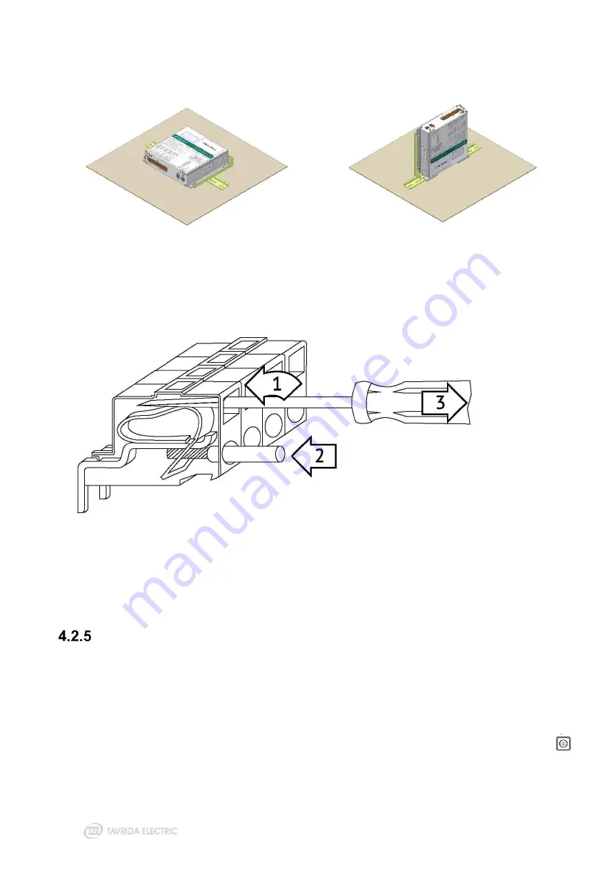
Figure 145
Installation to CM terminals
Wires are connected to the CM terminals by using a screwdriver (Figure 22). The terminals can accept solid
and stranded wire within the range 0.5-2.5 mm. The insulation stripping length shall be 6-10 mm. Insulated
auxiliary circuits shall provide 2 kV power frequency dielectric strength.
Installation of secondary cables between ISM and CM
Before connection CM to ISM the compliance between ISM type (shown on ISM serial number plate
– Figure
2) and CM (applicability of CM for particular type of ISM are shown on CM designation label
– Figure 4 and
CM packing label - Figure 21) shall be confirmed.
Warning! If the CM label does not show the correct ISM type connection shall not be established. It can lead
to damage of the ISM. Contact your nearest Tavrida Electric partner for replacement.
Secondary cables between ISM and CM shall be installed according to the following instructions (
–
Figure 149). To achieve best possible protection against electromagnetic influences. The earthing point 3
shall be as close as possible to the CM. Unshielded parts of wires shall be not longer than 10 cm. Connections
between the end of cable shields and ISM earthing points shall be not longer than 5 cm.
Содержание VCB Series
Страница 1: ...COMPATIBLE SERIES USER GUIDE...
Страница 2: ......
Страница 4: ......
Страница 5: ...1 Product description...
Страница 13: ...13 2 Nameplates and seals...
Страница 18: ...18 3 Product handling...
Страница 37: ...4 Installation...
Страница 51: ...51 Figure 86 ISM15_MD insulation clearances 75 kV BIL Figure 87 ISM15_MD insulation clearances 95 kV BIL...
Страница 87: ......
Страница 88: ...5 Commissioning...
Страница 94: ...94 Figure 155 The connection points of the contact resistance meter...
Страница 95: ......
Страница 96: ...6 Operation...
Страница 100: ...7 Maintenance and troubleshooting...
Страница 105: ......
Страница 106: ...8 Disposal...
Страница 109: ...109 Appendix 2 Overall Drawings...
Страница 110: ...110 Dimensions of Indoor Switching Modules ISM15_LD_1 67 PCD 150 mm Weight 34 kg ISM15_LD_1 55 PCD 210 mm Weight 36 kg...
Страница 111: ...111 ISM15_LD_1 80 two lower terminals continuous busbar PCD 150 mm Weight 36 kg ISM15_LD_1 90 PCD 180 mm Weight 36 kg...
Страница 112: ...112 ISM15_LD_3 Weight 13 kg ISM15_LD_6 PCD 133 mm Weight 55 kg...
Страница 113: ...113 ISM15_LD_8 PCD 210 mm Weight 26 kg...
Страница 114: ...114 ISM15_MD_1 150_L PCD 150 mm Weight 33 kg ISM15_MD_1 210_L PCD 210 mm Weight 35 kg...
Страница 115: ...115 ISM15_MD_3 Weight 13 kg ISM15_Shell_2 150_L PCD 150 mm Weight 51 kg...
Страница 120: ...120 ISM15_HD_1 275 PCD 275 mm Weight 72 kg ISM25_LD_1 210_Par2 PCD 210 mm Weight 36 kg...
Страница 123: ...123 ISM25_LD_2 2 PCD 150 mm Weight 37 kg ISM25_LD_3 Weight 14 kg...
Страница 124: ...124 ISM25_LD_3 with CBkit_Ins_3 installed Weight 14 5 kg upper busbar shown for reference and is not supplied...
Страница 125: ...125 Dimensions of Control Module CM_16_1 Par1_Par2_Par3_Par4_Par5 Weight 1 kg...
Страница 127: ...127 Dimensions of Interlocking Kits CBkit_Interlock_1 CBkit_Interlock_3...
Страница 128: ...128 CBkit_Interlock_4 CBkit_Interlock_5...
Страница 129: ...Appendix 3 Secondary Schemes...
Страница 130: ...130...
Страница 131: ...131...
Страница 132: ...132...
Страница 133: ...133...
Страница 134: ...134...
Страница 135: ...135...
Страница 136: ...136...
Страница 137: ...137...
Страница 138: ...138...
Страница 139: ...139...
Страница 140: ...140...
Страница 142: ...Bartlett...