24
TASCAM Model 24
2 – Names and Functions of Parts
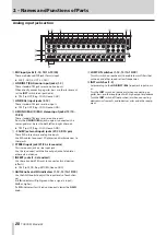
Analog output adjustment section
T
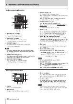
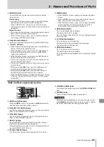
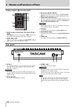
MUTE switches and indicators (SUB, MON 1, MON 2,
MAIN)
When
MUTE
switches are on (pushed in,
MUTE
indicators lit),
signals to the corresponding output jacks are muted.
Y
MAIN switch (SUB)
When this switch is on (pushed in), the
SUB OUTPUT L/R
jack
output signal is sent to the MAIN MIX L/R bus.
U
AFL switches (MON 1/MON 2)
When these switches are on (pushed in), the
AUX OUTPUT
MON 1/2
jack output signals are sent to the PFL/AFL L/R bus.
I
SD MAIN MIX RETURN switch
When this switch is on (pushed in), playback of stereo master
files recorded on the SD card is output from the
MAIN OUT-
PUT
and
AUX OUTPUT MON 1
/
2
jacks.
ATTENTION
Be aware that when this switch is on (pushed in), the sound
of the MAIN MIX L/R bus is not output.
O
SUB fader
Use to adjust the output level of the
SUB OUTPUT
jacks.
P
MON 1/MON 2 faders
Use to adjust the output levels of the
AUX OUTPUT MON 1/2
jacks.
A
MAIN fader
Use to adjust the output level of the
MAIN OUTPUT
jacks.
Rear panel
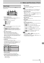
S
USB port
This is a B-type USB port. Use a USB cable (Type-A to Type-B)
to connect the unit to a computer. (See “Connecting with a
ATTENTION
The unit should be connected directly to the computer, not
through a USB hub. Moreover, noise could be picked up if the
cable is too long.
D
AC IN connector
Connect the included power cord here.
F
POWER switch
Press to turn the unit on and off.
V
CAUTION
Before turning the unit on, lower the volumes of connected
equipment to their minimum levels.
Failure to do so might cause sudden loud noises, which could
harm your hearing or result in other trouble.
NOTE
Do not do this when the unit is operating (including record-
ing, playing back or writing data to an SD card). Doing so
could cause proper recording to fail and recorded data to be
lost.
Содержание 24
Страница 160: ...160 TASCAM Model 24 Block diagram Sch ma fonctionnel Diagrama de bloques...
Страница 162: ......


