background image


6.   DATA


Tapflo sanitary pump series


43


6.3.


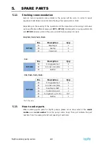
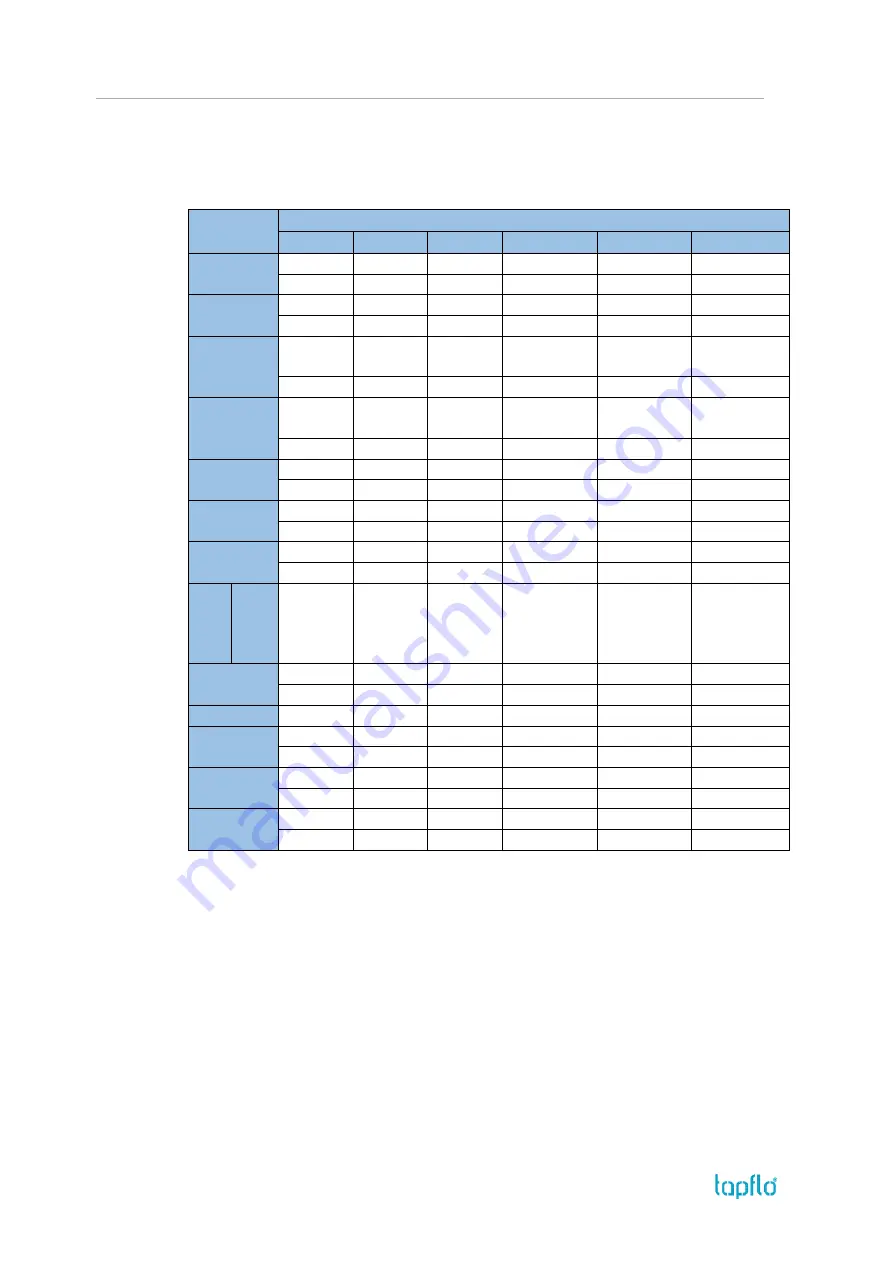
Dimensions 


Dimensions in mm (where other is not indicated)  

Dimensions in inch (where other is not indicated) 

General dimensions only, ask us for detailed drawings. Changes reserved without notice. 


Dimension 

PUMP SIZE 

T30 

T80 

T125 

T225 

T425 

T825 

169 

295 

320 

404 

468 

750 

6.7 

11.6 

12.6 

15.9 

18.4 

29.5 

153 

303 

328 

412 

476 

760 

11.9 

12.9 

16.2 

18.7 

29.9 

313 

393 

458 

647 / 792**  808 / 950** 

1288 / 

1495** 

12.3 

15.5 

18 

25.5 / 31.1 

31.8 / 37.4 

50.7 / 58.8 

240 

294 

350 

528 / 690**  664 / 775** 

1034.5 / 

1270** 

9.4 

11.6 

13.8 

20.6 / 27.2 

26.1 / 30.5 

40.7 / 50 

34 

10 

10 

10 

10 

20 

1.3 

0.4 

0.4 

0.4 

0.4 

0.8 

30 

30 

30 

30 

30 

60 

1.2 

1.2 

1.2 

1.2 

1.2 

2.4 

48 

74.5 

82.5 

86.5 / 70**  98.5 / 140**  206.5 / 165** 

1.9 

2.9 

3.2 

3.4 / 2.8 

3.9 / 5.5 

8.1 / 6.5 

J   

TC

1


DIN

2


SMS

3


RJT

4


25 

DN20  

25 

¾" 

25 

DN25 

25 

1" 

38  

DN40 

38 

1 ½" 

51 

DN50 

51 

2” 

70  

DN65 

63.5  

3” 

76.1 

DN80 

76.1 

3 ½” 

Ø

25x13 

0.4 

0.4 

0.4 

0.4 

0.4 

1x0.5 

G 1/8” 

G ¼” 

G ¼” 

G ½” 

G ½” 

G ½” 

Ø

M* 

50.5 

50.5 

50.5 

64 

91 

98 / 119** 

2.0 

2.0 

2.0 

2.5 

3.6 

3.9 / 4.7 

Ø

N* 

22.6 

22.6 

35.6 

48.6 

66.8 

72.9 / 100** 

0.9 

0.9 

1.4 

1.9 

2.6 

2.9 / 3.9 

125 

275 

300 

384 

448 

710 

4.9 

10.8 

11.8 

15.1 

17.6 

28 


*  = Dimensions for standard clamp connections only  
** = Dimensions with flap valves and heavy duty valve cup version 
1 = Clamp connections according to SMS3017 (T30 – T225) / ISO2037 (T425-T825) 
2 = Threaded connections according to DIN 11851  
3 = Threaded connections according to SMS 1145 
4 = Threaded connections according to BS 4825-5


Содержание Sanitary Series

Страница 1: ...itary Series Diaphragm Pumps edition 2018 rev 1 Original Instruction Read this instruction manual carefully before you install and operate the pump Pump models T TX30 T TX80 T TX125 T TX225 T TX425 T TX825 ...

Страница 2: ...d safety 10 1 7 1 Protection 10 1 7 2 Explosion hazardous environments ATEX 11 1 7 3 Air pressure 11 1 7 4 Noise level 11 1 7 5 Temperature hazards 12 1 8 Air connection 12 1 8 1 Air treatment system 12 1 8 2 Air quality classes 13 1 9 Installation example 13 1 10 Recommended installations 14 1 10 1 Flooded 14 1 10 2 Self priming 14 2 OPERATION 15 2 1 Before starting the pump 15 2 2 Starting and o...

Страница 3: ...isassembly procedure 24 3 8 T80 T425 assembly of the pump 27 3 8 1 Test run 28 4 OPTIONS 29 4 1 Valve options 29 4 1 1 Flap valves 29 4 1 2 Ball cup valves 30 4 2 Heating jacket 30 4 3 Magnetic ball lifters 31 5 SPARE PARTS 32 5 1 T30 Spare parts drawing 32 5 2 T30 Spare parts list 32 5 3 T80 T125 Spare parts drawing 33 5 4 T80 T125 Spare parts list 33 5 5 T80 T125 Spare parts options 34 5 6 T225 ...

Страница 4: ...Pump code 41 6 DATA 42 6 1 Capacity curves 42 6 2 Capacity changes 42 6 3 Dimensions 43 6 4 Technical data 45 6 5 Tightening torques 45 6 6 Permitted loads on manifolds 46 7 WARRANTY 47 7 1 Warranty form 47 7 2 Returning parts 48 7 3 Warranty 48 ...

Страница 5: ...claration SANITARY AIR OPERATED DIAPHRAGM PUMPS The object of the declaration described above is in conformity with the relevant Union harmonization legislation Directive 2006 42 EC of European Parliament and of the Council of 17 May 2006 on machinery amending Directive 95 16 EC Mr Michał Śmigiel is authorized to compile the technical file Tapflo Sp z o o ul Czatkowska 4b 83 110 Tczew Signed for a...

Страница 6: ...der the sole responsibility of the manufacturer Object of declaration CONDUCTIVE AIR OPERATED DIAPHRAGM PUMPS The object of the declaration described above is in conformity with the relevant Union harmonisation legislation Directive 2006 42 EC of European Parliament and of the Council of 17 May 2006 on machinery Directive 2014 34 EU of the European parliament and of the council of 26 February 2014...

Страница 7: ...e and limb may occur Observe these instructions and proceed with utmost caution in these situations Inform also other users of all safety instructions In addition to the instructions in this instruction manual the general safety and accident prevention regulations must be observed This signal stands at points in this instruction manual of particular importance for compliance with regulations and d...

Страница 8: ...taneously transmits the air pressure to the liquid in the second chamber on the right of the housing pushing it towards the discharge port During each cycle the air pressure on the back of the discharging diaphragm is equal to the head pressure on the liquid side Tapflo diaphragm pumps can therefore be operated against a closed discharge valve with no negative effect to the life of the diaphragms ...

Страница 9: ...quipment is to be stored prior to installation place it in a clean location The pump should be stored in an ambient temperature of 15 C 59 F to 25 C 77 F and relative humidity below 65 It should not be exposed to any heat source e g radiator sun as this could result in a negative way on the tightness of the pump Do not remove the protective covers from the suction discharge and air connections whi...

Страница 10: ...ways use as short suction pipe as possible Avoid air pockets which can arise with long piping 1 6 2 Connection of discharge pipe For this connection it is only recommended a simple and positive flow connection Use a hose or flexible piping minimum one meter between the discharge connection and any rigid fixed piping Coil the hose at least one turn All components hose pipe valves etc on the dischar...

Страница 11: ...he earth wire to earth and also make sure that other equipment like hoses pipes containers etc are properly earthed connected Dry run in ATEX pump ATEX approved pumps can run dry without increasing the risk of creating potential ignition sources Nevertheless dry run periods should be decreased to minimum as they increase the wear of parts inside of the pump What is more when running dry e g during...

Страница 12: ... pumping such cold products Also in such case when a pump is not operational it should be drained of all liquid Bear in mind that the viscosity of the product changes with temperature This has to be taken into consideration when selecting the pump 1 8 Air connection Screw the air hose into the air intake on the centre block of the pump with for example a bayonet coupling For best efficiency use th...

Страница 13: ...erosol and vapour mg m 0 1 0 5 µm 0 5 1 µm 1 5 µm 0 As specified by the equipment user or supplier and more stringent than class 1 1 20 000 400 10 70 0 01 2 400 000 6 000 100 40 0 1 3 90 000 1 000 20 1 4 10 000 3 5 5 100 000 7 6 5 10 7 5 10 0 5 8 0 5 5 9 5 10 X 10 10 10 1 9 Installation example 1 Gate valve compressed air 2 Filter and pressure regulator 3 Flexible hose 4 Needle valve 5 Flexible pi...

Страница 14: ...re may cause premature diaphragm failure and irregular pump operation 1 10 2 Self priming The Tapflo pump is designed to pull a high vacuum It is able to evacuate an empty suction pipe without any damage to the pump The suction lift is up to 5 meters 16 4 ft from an empty suction pipe and up to 8 meters 26 2 ft from a wetted pipe The suction capability depends on the pump size see chapter 6 Data N...

Страница 15: ... the air supply by using a needle valve and a pressure regulator The performance can also be adjusted by normal flow control on the discharge side of the system 2 2 1 Dry running Although the pump is prepared for dry running it is important to have in mind that long periods of dry run may cause damage to the air valve and circlips Also an empty pump should operate at low speeds controlled by a nee...

Страница 16: ... pumps pressure 2 4 Cleaning of the pump 2 4 1 CIP Cleaning In Place The importance of easy cleaning is especially great in hygienic applications Tapflo sanitary pumps are designed for CIP cleaning in place This allows the pump to be internally cleaned without disassembly The pump can be cleaned by flushing through with a CIP fluid usually a mild solution of sodium hydroxide and a sanitizing addit...

Страница 17: ...ith a hygienic stand enabling 360 rotation of the pump unit 1 Disconnect the pump from the piping 2 Simply loosen the two socket head cap screws pos 174 see chapter 5 SPARE PARTS rotate the pump 180 and let the remaining fluid drain off The airline may be left connected during this operation 3 Rotate back to normal position connect the pump with the piping and fix the socket head cap screws pos 17...

Страница 18: ...g pump can be an indication of wearing parts see chapter 3 4 Location of faults below Leaking liquid from the pump and changes of performance may also be detected Routine inspections should be conducted frequently 3 3 Complete inspection The intervals for a complete inspection depend upon the operation conditions of the pump The characteristics of the liquid temperature materials used in the pump ...

Страница 19: ...mprove air quality see chapters 1 7 1 and 2 2 2 Bad flow pressure Pressure fall in air supply Pressure losses on suction side Air supply air valve leaking Increase air pressure via a filter regulator Check change installation on suction side Check repair replace air supply air valve Suction or air connection blocked Check clean air supply suction connection Muffler is blocked Check clean replace m...

Страница 20: ...sconnect the air supply and then the suction and discharge connections 3 5 2 Disassembly procedure Fig 3 5 1 Unscrew and remove two tri clamps 138 connecting the outlet manifold 132 to the housings 11 Fig 3 5 2 Take off the outlet manifold 132 and remove the valve balls 23 and sealing 18 Fig 3 5 3 Unscrew and remove two tri clamps 138 connecting the inlet manifold and stand 131 to the housings 11 ...

Страница 21: ...e diaphragm 15 Fig 3 5 7 Turn the pump over remove the domed nuts 37 and washers 38 Take off the second housing 11 Fig 3 5 8 Take out the pin screws 14 and unscrew the second diaphragm 15 Fig 3 5 9 Using pliers remove both circlips 27 from the centre block 12 Attention While doing this cover yourself with your other hand as the circlip easily flips away ...

Страница 22: ...mber in order to assemble the pump correctly Fig 3 6 1 When putting the air valve 61 into the centre block 12 apply some water or alcohol on the O rings to provide smooth insertion of the air valve It is recommended to use a pressing device for this operation NOTE When inserting the T30 size air valve replace the shaft with a screw and a nut to make sure the air valve assembly remains properly fas...

Страница 23: ...ure and with the appropriate torque NOTE Keep in mind to periodically retighten pin screw s nuts Fig 3 6 6 When fastening the tri clamps apply some FDA grade lubricate on the thread 3 6 1 Test run We recommend you to conduct a test run of the pump before installing it in the system so no liquid gets wasted if the pump leaks or perhaps does not start accordingly to wrong assembly of the pump After ...

Страница 24: ...PARTS 3 7 1 Before the disassembly procedure Be sure to drain all liquid from the pump Cleanse or neutralize the pump thoroughly Disconnect the air supply and then the suction and discharge connections 3 7 2 Disassembly procedure Fig 3 7 1 Unscrew and remove two tri clamps 138 connecting the manifold 132 to the housings 11 Fig 3 7 2 Take off the manifold 132 and remove the valve balls 23 and seali...

Страница 25: ...ve the valve balls 23 and sealing 18 Loosen the socket head cap screws 174 and take off the pump from the stand 17 Fig 3 7 5 Unscrew the domed nuts 37 and remove the housing 11 from one side of the pump Fig 3 7 6 Turn the pump over remove the domed nuts 37 and washers 38 Take off the second housing 11 Fig 3 7 7 Unscrew the diaphragm 15 from one side of the pump ...

Страница 26: ...r other hand as the circlip easily flips away Fig 3 7 10 Press out the air valve 61 by means of a pressing device Be careful not to damage the brass edges of the air valve b Plate mounted air valve TX125 from s n 0907 T TX225 T TX425 Fig 3 7 11 Unscrew plate screws 2711 from both sides of the centre body 12 and take out the left and right plate 271 Fig 3 7 12 Press out the air valve 61 by means of...

Страница 27: ...f the mounting tool Use a pressing device to remove the air valve cylinder from the centre body The pump is now completely disassembled Check all components for wear or damage and replace if necessary When air valve is removed from the centre body check the external O rings 6 x pos 30 condition and replace if necessary 3 8 T80 T425 assembly of the pump The assembly procedure is done in the reverse...

Страница 28: ...ust align with the holes in the centre block 12 Sometimes it is necessary to turn the diaphragm back a little bit in order to align the holes Fig 3 8 4 When fastening the domed nuts remember to do it according to the tightening procedure and with the appropriate torque NOTE Keep in mind to periodically retighten pins crew s nuts Fig 3 8 5 When fastening the tri clamps apply some FDA grade lubricat...

Страница 29: ...e for pumping water like products If a liquid has low viscosity the valve will open and close very fast with no shock absorption that is provided by viscous products Also dry running of the pump for longer periods will cause rapid valve wear and eventually pump stopping Additional different parts T225 and T425 No Art no Q ty Description 6 xxx 24H 4 Flap valve complete 241H 242H 1 6 xxx 241H 4 Flap...

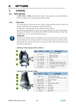
Страница 30: ...housing ball cup valves 6 xxx 18F 8 3 clamp seal 6 xxx 1381 4 3 clamps 6 xxx 22B 4 Valve ball stop 6 xxx 182 4 O ring 6 xxx 17C 1 Pump Stand 4 2 Heating jacket The heating jacket is a great option when the pumped product tends to solidify at lower temperatures e g chocolate or paraffin When the pump has finished its duty and is left for some time without operation the product can solidify inside T...

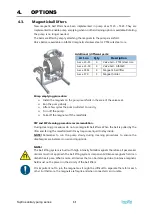
Страница 31: ... few cycles the pump will start to run dry Turn off the pump Take off the magnets off the manifolds CIP and SIP cleaning procedure recommendation During cleaning procedures do not use magnetic ball lifters When the ball is pulled by the lifter and facing the manifold wall it may trap some liquid to stay inside NOTE Remember to run the pump slowly during cleaning procedures to ensure the diaphragms...

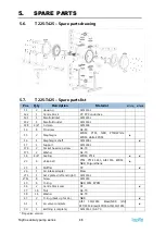
Страница 32: ...2 1 Manifold outlet AISI 316L 138 4 3 clamp AISI 304 14 4 Pin screw A4 80 15 2 Diaphragm EPDM PTFE NBR PTFE White EPDM white EPDM X 16 1 Diaphragm shaft AISI 316L 18 4 Sealing EPDM PTFE X X 23 4 Valve ball PTFE AISI 316 EPDM NBR PU X 25 1 Muffler PP X 27 2 Circlip Cr3 coated steel 30 6 O ring NBR FKM EPDM 37 8 Nut A4 70 38 8 Washer A4 70 61 1 Air valve complete AISI 316L FKM Brass NBR Brass EPDM A...

Страница 33: ...E White EPDM white EPDM X 16 1 Diaphragm shaft AISI 304L X 17 1 Support AISI 304L 174 2 Socket head cap screw A4 70 175 2 Washer A4 70 18 4 Sealing EPDM PTFE X X 23 4 Valve ball PTFE PTFE 1635 AISI 316 EPDM NBR PU X 25 1 Muffler PP X 26 1 Air intake adapter Brass 27 2 Circlip Cr3 coated steel 30 6 O ring NBR FKM EPDM 36 2 Centre block seal PE X 37 12 Nut A4 70 38 12 Washer A4 70 47 2 4 O ring back...

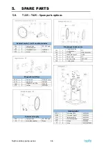
Страница 34: ...all lifters 23 15 4 Valve ball PTFE SS core 23 59 4 Valve ball AISI420 95M 4 Magnetic ball lifter PE1000 170 2 Holder AISI316L External air supply 124 1 Center block PP PP Cond 26 2 Air intake adapter Brass Diaphragm stroke sensor 121 1 Centerblock for stroke sensor PP 751 1 O ring NBR FKM EPDM 74 1 Inductive sensor CuZn 75 1 Sensor cap PP 76 1 Sensing plate AISI 316L 750 1 Cable gland PP Heating ...

Страница 35: ...x 16 1 Diaphragm shaft AISI 304L x 17 1 Support AISI 304L 174 2 Socket head cap screw A4 70 175 2 Washer A4 70 18 4 8 Sealing EPDM PTFE x x 23 4 Valve ball PTFE PTFE 1635 AISI 316 EPDM NBR Polyurethane x 25 1 Muffler PP x 26 1 Air intake adapter Brass 271 1 Set 2 plates left and right AISI 316L 2711 8 Screw AISI 316 30 6 O ring NBR FKM EPDM 36 2 Centre block seal PE x 37 16 Nut A4 70 38 16 Washer ...

Страница 36: ...95M 4 Magnetic ball lifter PE1000 170 2 Holder AISI316L External air supply 124 1 Center block PP PP Cond 26 2 Air intake adapter Brass Diaphragm stroke sensor 121 1 Centerblock for stroke sensor PP 751 1 O ring NBR FKM EPDM 74 1 Inductive sensor CuZn 75 1 Sensor cap PP 76 1 Sensing plate AISI 316L 750 1 Cable gland PP Heating jacket 1110L 1 Housing left AISI316L 1110R 1 Housing right AISI316L 131...

Страница 37: ...4 18H 8 Sealing PTFE EPDM 241H 4 Flap valve seat AISI316L 242H 4 Flap AISI316L 24H 4 Flap valve complete 241H 242H AISI316L Ball cup valves 11C 2 Housing AISI316L 131C 1 Inlet manifold AISI316L 132C 1 Outlet manifold AISI316L 138 8 Tri clamp AISI304 17V 1 Stand AISI304 18F 8 Sealing PTFE EPDM 182 4 Stopper O ring FEP FKM 22B 4 Valve ball stopper AISI316L 24B 4 Ball valve cup AISI316L ...

Страница 38: ...16L 132 1 Manifold outlet AISI 316L 14 8 Pin screw A4 80 141 32 Manifold screw A4 70 15 2 Diaphragm EPDM PTFE NBR 16 1 Diaphragm shaft AISI 304L 17 1 Stand AISI 304 174 2 Socket head cap screw A2 70 176 2 Blocking pin AISI316L 1791 2 Eye bolt A2 70 1792 2 Eye bolt washer A2 70 18 4 Sealing PTFE 23 4 Valve ball PTFE EPDM 25 1 Muffler PP 26 1 Air intake adapter Brass 27 2 Circlip Cr3 coated steel 30...

Страница 39: ...ISI 316 FKM PET FKM 5 11 T825 Spare parts options Air valve reinforcement 122 1 Center block PP 271 1 Set of 2 reinforcement plates AISI 316L 2711 8 Screws A4 70 Flap valves 11H 2 Housing AISI316L 13H 2 In outlet manifold AISI316L 138 8 Tri clamp DN100 AISI304L 138H 4 Tri clamp DN150 AISI304L 17H 1 Stand AISI304L 18 8 Sealing DN100 EPDM 18H 4 Sealing DN150 EPDM 241H 4 Flap valve seat AISI316L 242H...

Страница 40: ...t are subject to wear T30 T80 T125 T225 T425 Pos Description Q ty KIT LIQ 15 Diaphragm 2 18 Sealing 4 23 Valve ball 4 T30 Pos Description Q ty KIT AIR 18 O ring gasket set 4 61 Air valve complete 1 25 Muffler 1 T80 T125 T225 T425 Pos Description Q ty KIT AIR 18 O ring gasket set 4 61 Air valve complete 1 16 Diaphragm shaft 1 36 Centre block seal 2 47 O ring back up for 36 2 4 25 Muffler 1 For T125...

Страница 41: ...2 IV Material of wetted metal parts S stainless steel AISI 316L V Material of diaphragms E EPDM W White food grade EPDM N NBR nitrile rubber T PTFE Z PTFE with white back food grade B PTFE TFM 1705b VI Material of valve balls E EPDM N NBR nitrile rubber T PTFE S AISI 316 stainless steel P PU polyurethane K Ceramic B PTFE TFM 1635 blank flap valve version VII Special executions 1 Optional in outlet...

Страница 42: ...sities and suction lifts Example A flow of 30 litre minute is desired The discharge pressure is calculated to 25 mWC We choose a T80 pump It requires an air pressure of 4 bar and will consume approximately 0 20 Nm3 of air per minute Recommended flow is half of the max flow e g recommended flow for a T80 is 40 l min 6 2 Capacity changes Capacity changes at different suction lifts Capacity changes a...

Страница 43: ...0 4 0 4 0 8 H 30 30 30 30 30 60 1 2 1 2 1 2 1 2 1 2 2 4 I 48 74 5 82 5 86 5 70 98 5 140 206 5 165 1 9 2 9 3 2 3 4 2 8 3 9 5 5 8 1 6 5 J TC1 DIN2 SMS3 RJT4 25 DN20 25 25 DN25 25 1 38 DN40 38 1 51 DN50 51 2 70 DN65 63 5 3 76 1 DN80 76 1 3 ØK 9 9 9 9 9 25x13 0 4 0 4 0 4 0 4 0 4 1x0 5 L G 1 8 G G G G G ØM 50 5 50 5 50 5 64 91 98 119 2 0 2 0 2 0 2 5 3 6 3 9 4 7 ØN 22 6 22 6 35 6 48 6 66 8 72 9 100 0 9 ...

Страница 44: ...6 DATA Tapflo sanitary pump series 44 ...

Страница 45: ... about 15 less volume With stainless steel valve balls other materials may reduce suction Please consult us in this matter Flap valve version COMPONENT MATERIAL Wetted metal details Stainless steel AISI 316L electro polished T825 glass blasted Centre block not wetted PP PP conductive aluminium Diaphragms PTFE PTFE with white back EPDM white EPDM NBR NBR grey Valve balls PTFE EPDM NBR AISI 316 PU C...

Страница 46: ...tion Load N inlet outlet Moment of force inlet outlet Nm X 31 6 3 Y 31 6 3 Z 31 6 3 T125 Direction Load N inlet outlet Moment of force inlet outlet Nm X 35 7 3 Y 35 7 3 Z 35 7 3 T225 Direction Load N inlet outlet Moment of force inlet outlet Nm X 43 8 8 Y 43 8 8 Z 43 8 8 T425 Direction Load N inlet outlet Moment of force inlet outlet Nm X 56 11 5 Y 56 11 5 Z 56 11 5 T825 Direction Load N inlet out...

Страница 47: ...ype Serial No see name plate or stamped on pump housing Description of the fault The installation Liquid Temperature C Viscosity cPs Spec grav kg m3 pH value Content of particles of max size mm Flow l min Duty h day No of starts per day Discharge head mWC Suction head lift m Air pressure bar Quality of the air filter micron lubrication Other Place for sketch of installation ...

Страница 48: ... for those purposes set out in any invitation to render documents or other documents specifically made available to Tapflo before entering into this agreement c high quality materials are used in the construction of the pumps and that machining and assembly are carried out to the highest standards Except as expressly stated above Tapflo makes no warranties express or implied concerning the product...

Страница 49: ...or components will become the property of Tapflo 7 The products are built in accordance with standard CE normative and are tested where applicable by Tapflo Approval and tests by other control authority are for the customer s account The products shall not be considered defective in materials design or workmanship if they need to be adapted changed or adjusted to conform to national or local techn...

Страница 50: ...o sk Slovenia Tapflo GmbH Tel 386 68 613 474 sales tapflo hr Spain Tapflo Iberica Tel 34 91 8093182 avives tapfloiberica es South Africa Tapflo Pty Ltd Tel 27 31 701 5255 sales tapflo co za Turkey Tapflo Makina Ltd Tel 90 216 467 33 11 sales tapflo com tr Ukraine TOB Tapflo Tel 380 44 222 68 44 sales tapflo com ua Uzbekistan Tapflo Uzbekistan Tel 998 712370940 sales tapflo uz United Kingdom Tapflo...

Отзывы: