background image

LD-G-11 / LD-W-11

English

Page 29

Safety instructions

Mechanical hazards

Cut wires can have sharp ends and can cause serious injuries. Watch
out for sharp edges when you pick up the PCB.
Visibly damaged parts can cause unpredictable danger. Do not use
damaged parts: recycle and replace them with new ones.

Electrical hazards

§


Touching powered, live components,

§


touching conducting components which are live due to malfunction,

§


short circuits,

§


connecting the circuit to another voltage than specified,

§


impermissibly high humidity,

§


condensation build up

can cause serious injury due to electrical shock. Take the following
precautions to prevent this danger:

§


Never perform wiring on a powered module.

§


Mounting the module should only be done in closed, clean, dry
rooms. Beware of humidity.

§


Only use low power for this module as described in this manual and
only use certified transformers.

§


Connect transformers and soldering irons only in approved mains
sockets installed by an authorised electrician.

§


Observe cable diameter requirements.

§


After condensation build up, allow a minimum of 2 hours for
dispersion.

§


Use only original spare parts if you have to repair the module.

Содержание LD-G-11

Страница 1: ...la n Locdecoder voor gelijkstroommotoren Motorola format n Art Nr 22 01 080 n n n Anleitung LD W 11 n Manual Lokdecoder für Wechselstrommotoren Motorola Format n Mode d emploi Locomotive Decoder for AC engines Motorola format n Handleiding Décodeur pour locomotive avec moteur alternatif Format Motorola n Locdecoder voor wisselstroommotoren Motorola format n Art Nr 22 01 079 n ...

Страница 2: ... any means electronic or mechanical including photocopying without prior permission in writing from Tams Elektronik GmbH Subject to technical modification 09 2006 Tams Elektronik GmbH Tout droits réservés en particulier les droits de reproduction et de diffusion ainsi que le traduction Toute duplication ou reproduction sous quelque forme que ce soit nécessite l accord écrit de la societé Tams Elek...

Страница 3: ...cations 36 Checking the package contents 36 Required tools and materials 36 Safe and correct soldering 37 Mounting the locomotive decoder 38 Programming the locomotive decoder 41 Operation 47 FAQ 48 Manufacturer s note 49 Certification 49 Conditional warranty 49 Connections Fig 1 2 and 3 I Circuit Diagram Fig 4 II Pages I to II in the centre of this handbook are removeable ...

Страница 4: ...ase pass on the manual with it Intended use The locomotive decoder is designed for mounting in a model train with DC motor LD G 11 or AC motor LD W 11 It evaluates the Motorola format data sent by the digital central unit to its address and controls the locomotive s motor and additional functions The module should not be mounted by children under the age of 14 Reading understanding and following t...

Страница 5: ...e than specified impermissibly high humidity condensation build up can cause serious injury due to electrical shock Take the following precautions to prevent this danger Never perform wiring on a powered module Mounting the module should only be done in closed clean dry rooms Beware of humidity Only use low power for this module as described in this manual and only use certified transformers Conne...

Страница 6: ...carefully when soldering and remove liquid solder with a thick wet rag or wet sponge from the soldering tip Dangerous environments A working area that is too small or cramped is unsuitable and can cause accidents fires and injury Prevent this by working in a clean dry room with enough freedom of movement Other dangers Children can cause any of the accidents mentioned above because they are inatten...

Страница 7: ...netic tolerance and meets legal requirements To guarantee the electromagnetic tolerance you must take the following precautions Connect the transformer only to an approved mains socket installed by an authorised electrician Make no changes to the original parts and accurately follow the instructions print layout and circuit diagram included with this manual Use only original spare parts if you hav...

Страница 8: ...tic recognition of the analogue mode can be switched off by programming the decoder accordingly The decoder is not suitable for being operated in analogue model railway layouts run with an D C speed control The decoder evaluates the data received in such layouts as braking section the locomotive therefore does not run In analogue mode the decoder reacts to the analogue changing direction signal Th...

Страница 9: ... the decoder chooses the optimal value can be altered by programming the decoder accordingly Direction of motion When changing the direction in digital operation the existing direction is saved and so retained even if the central unit does not send absolute driving data e g in Motorola I format In order to change the direction of travel in analogue operation a voltage impulse is applied to the rai...

Страница 10: ...mum velocity the decoder generates a velocity characteristic corresponding to the opposite figure This characteristic allows a good fine tuning of the speed in the lower speed range Shunting gear The auxiliary function F4 allows you to switch into the shunting gear mode In the shunting gear mode the velocity of all speed levels is reduced to ca 25 compared to the standard velocity Acceleration and...

Страница 11: ...fers in some points according to the differences between both formats In particular programming the decoder on a DCC programming track is not possible Online programming Alternatively to the CV programming it is possible to program the address and the driving characteristics online This means Right after starting the programming mode your can enter the new address and directly save it While progra...

Страница 12: ...rative humidity allowed max 85 Dimensions approx 22 x 17 x 6 mm Weight approx 1 8 g Checking the package contents Check the contents of the package for completeness after unpacking one decoder one manual N B For technical reasons it is possible that the PCB is not completely inserted This is not a fault Required tools and consumables Make sure you have the following tools and materials ready for u...

Страница 13: ...acks or soldering eyes Apply the soldering tip to the soldering spot in such a way that the wire and the soldering eye are heated at the same time Simultaneously add solder not too much As soon as the solder becomes liquid take it away Hold the soldering tip at the spot for a few seconds so that the solder flows into the joint then remove the soldering iron The joint should be held still for about...

Страница 14: ...not be removed Motor and interference suppression devices are one unit If even one part is removed it can cause extreme interference Follow the connections diagrams fig 1 and 2 Solder the connection to the slider at point X1 and the connection to the housing to point X7 These two connections can be exchanged without effecting functionality Solder the connections to the motor at the points X9 and X...

Страница 15: ... the lamps to the return conductor for all functions point point X4 the lamps must be insulated The lamps must not make contact with metal parts of the locomotive Possible short circuit The locomotive decoder will be damaged in operation Connecting the LEDs The function outputs of the locomotive decoder switch against decoder ground For that reason you must connect the cathode of the LED to the ou...

Страница 16: ...plug you save disconnecting the connections and you do not need to solder at the locomotive The list shows how to connect the contacts of the interface connector to the connecting points of the locomotive decoder Contact Connection Colour of cable Connecting points 1 Motor connection 1 orange X9 2 Lighting back yellow X2 3 Not used or F1 green 4 Power supply left black X1 5 Motor connection 2 grey...

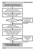
Страница 17: ... the decoder via CV programming it is sufficient to put the locomotive on a track section Please note You must connect the track oval or track section to the control unit s track output and not to control unit s output for the DCC programming track Reset the central unit by simultaneously pushing the buttons stop and go for some time or quickly switch f the central unit on and off First enter the ...

Страница 18: ...à Switch off the track voltage Operate the direction switch and hold it in that position Briefly push the button go As soon as the lighting flashes release the direction switch NO Intellibox Set the current address or address 80 Set all functions to off Start CV programming or one of 4 online programming steps Starting the programming mode Set address back to Motorola II format YES ...

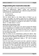
Страница 19: ... want to programm by setting the CV s number as Motorola locomotive address at your central unit 2 Operate the direction switch The locomotive s lighting stops flashing 3 Set the desired value of the CV by setting the CV s value as Motorola locomotive address at your central unit 4 Operate the direction switch again The locomotive s lighting starts flashing again Repeat the steps 1 to 4 for all CV...

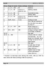
Страница 20: ... values for this CV 8 4 5 6 255 255 Motor frequency only for LD W 11 9 100 200 150 Analogue voltage needed for change of direction 10 15 Not used 16 43 0 255 Velocity table for velocity characteristic You can assign an individual motor voltage to each of the 27 speed levels 44 47 Not used 48 1 2 3 80 64 Lowest value of load control parameters only LD G 11 49 48 49 255 160 Highest value of load con...

Страница 21: ... or the starting and the maximum velocity the decoder first remains in the programming mode and you can alter and save your settings again The programming step is not finished until pushing stop Then the decoder returns to standard driving operation Connect your central unit to a track oval for online programming of the driving characteristics Please do not place other vehicles on the track oval w...

Страница 22: ...nction F1 The locomotive accelerates and brakes continuously By turning the speed control knob you can alter the acceleration and braking delay Speed level 0 à no delay Highest speed levelà maximum delay Switch on and off function f 0 once The settings are saved The locomotive s lighting flashes regularly Push Stop The programming mode is finished Setting the starting and the maximum velocity Star...

Страница 23: ...d off during braking the locomotive immediately runs with the speed level set at the central unit In Motorola I format the acceleration and brake delay is always active An emergency stop during acceleration and brake delay can be performed from the central unit by changing the direction of travel Switching the shunting gear In Motorola II format the shunting gear can be switched on and off via the...

Страница 24: ...tive runs too fast or too slow Possible cause Different locomotives drive differently with the same decoder settings à Adjust the decoder settings to the individual driving characteristics of the locomotive The locomotived does not react to F3 or F4 Possible cause The central unit is set to Motorola I format à Set the central unit to Motorola II format The locomotive does not run in analogue mode ...

Страница 25: ...f the product If he sells the product to another person he is responsible for passing on all the relevant papers and to give his name and address Certification This product conforms with the EC directive 89 336 EWG on electromagnetic radiation and is therefore CE certified Conditions of warranty This product is guaranteed for two years The warranty includes the correction of faults which can be pr...

Страница 26: ...components are added which are not described in the manual if the copper tracks or soldering eyes are damaged if damage occurs due to an overload of the module if connected to a incorrect voltage or current if damaged by other persons if damaged by faulty operation or if damaged by careless use or abuse if damaged by touching components before electrostatic discharging of the hands The following m...

Страница 27: ...ia le châssis de la loco Verbining van de verlichting met de locmassa X1 Schleifer Slider Frotteur Sleper X2 Beleuchtung Rückwärtsfahrt Lighting reverse direction Feux marche arrière Verlichting achteruitrijden X3 Beleuchtung Vorwärtsfahrt Lighting forward direction Feux marche avant Verlichting vooruitrijden X4 Rückleiter für alle Funktionen Return conductor for all functions Pole commun des fonc...

Страница 28: ...LD G 11 LD W 11 LD G 11 LD W 11 Seite Page Page Pagina II Seite Page Page Pagina II Fig 4 Schaltplan Circuit diagram Schéma de principe Schakelschema ...

Страница 29: ...ls Actuele informatie en tips n http www tams online de n n n n Garantie und Service Warranty and service n Garantie et service Garantie en service n n Tams Elektronik GmbH n Rupsteinstraße 10 D 30625 Hannover n fon 49 0 511 55 60 60 fax 49 0 511 55 61 61 n e mail info tams online de n ...

Отзывы: