Adjustments
Soft Adjustments
6-11
6.3
Soft Adjustments
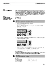
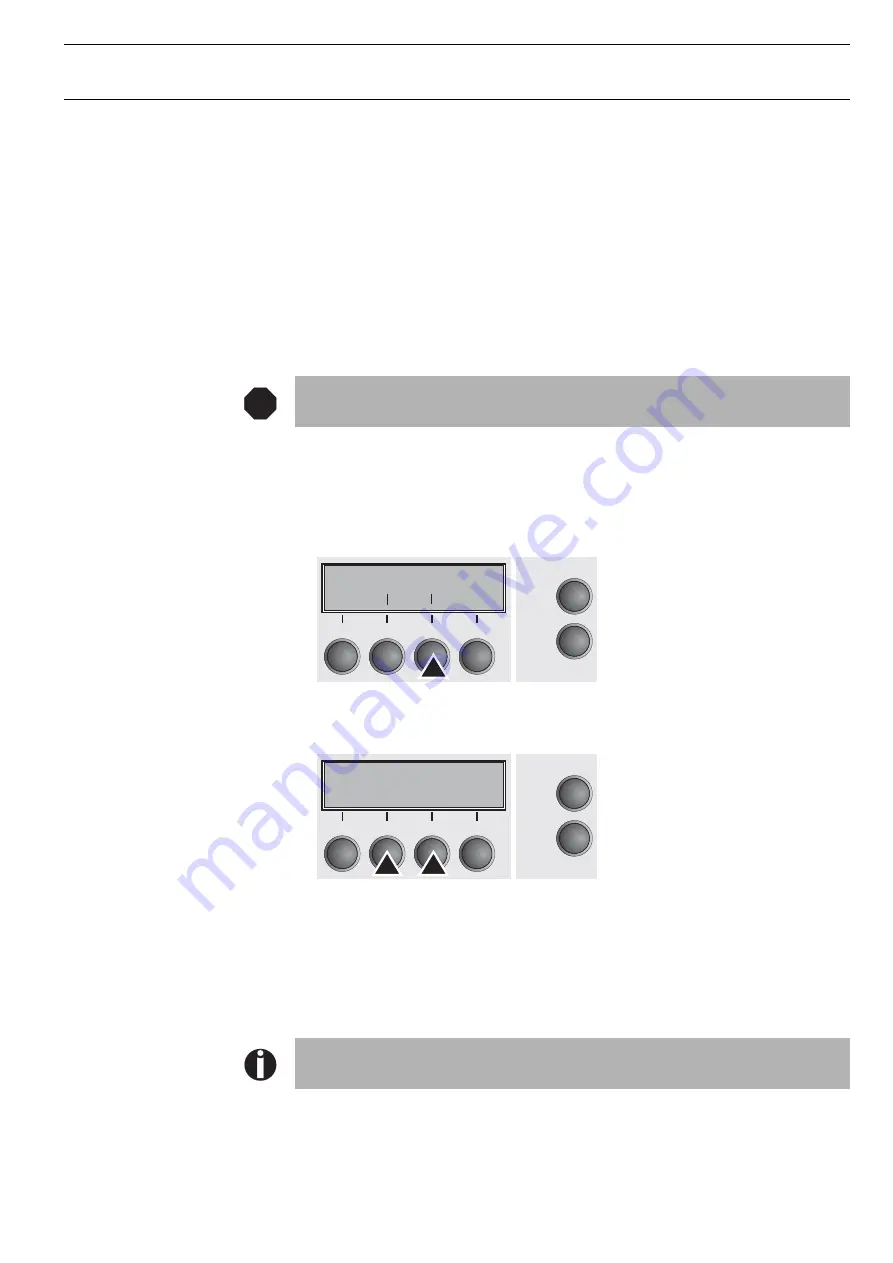
The printhead calibration is done with power on plus keys "Online" + "Setup" pressed,
then "Temp.cal" appears in the display. You can now set the printhead temperature.
These settings are stored on the printhead chip. This means that when you change
the logic board you do not have to calibrate the printhead again. As replacement prin-
theads are calibrated in the factory, you also do not have to perform a calibration
when you change the printhead.
6.3.1
Setting of Head
Temperature NDK9+
(Reference value)
Necessary tools:
Thermometer
– Make sure the printhead has room temperature
– Keep Top Cover Closed
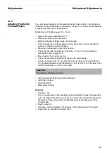
– Press keys ONLINE and SETUP simulaneously while Power On until TEST-
MODE is displayed shortly
– Press key “Temp. cal.“
– Set the actual head temperature (= room temperature) in a range between 15°C
and 30°C using the keys “<” and “>“
– Confirm your setting by pressing SET key. The new value is marked with a star
(*). (Leaving the item with key EXIT the value will not be stored)
– Leave TESTMODE by pressing ONLINE key
Recommendation:
You may use normal thermometer with a tolerance of 2 degrees max. Under normal
working conditions you do not need to adjust a yet installed printhead.
Caution:
Make sure the printhead has room temperature.
Attention:
Do not install/adjust a “hot” printhead.
Remark:
0 °C equals 32 °F
t
C
=0.55*(°F-32)°C
t
F
=(1.8*°C+32)°F
Example:
21 °C
≈
0.55 * (70 °F - 23)
70 °F
≈
(1.8 * 20°C + 32)
STOP
Print Temp.cal
Back Next
Online
Setup
2
1
3
4
Temp.cal=23 *
Set < > Exit
Online
Setup
2
1
3
4
Содержание 2365
Страница 1: ...Maintenance manual Matrix printer 2365 2380...
Страница 2: ...This page intentionally left blank...
Страница 8: ...This page intentionally left blank...
Страница 10: ...This page intentionally left blank...
Страница 20: ...This page intentionally left blank...
Страница 32: ...Mechanical Functions Functional Description 3 12 right mark mark mark...
Страница 35: ...Functional Description Electronic Functions 3 15 2365 2380 Electronic groups...
Страница 128: ...This page intentionally left blank...
Страница 134: ...Mechanical Adjustments Adjustments 6 6...
Страница 136: ...Electrical Adjustments Adjustments 6 8...
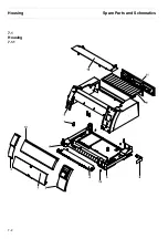
Страница 142: ...Housing Spare Parts and Schematics 7 2 7 1 Housing 7 1 1...
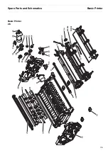
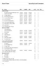
Страница 144: ...Basic Printer Spare Parts and Schematics 7 4 7 2 1 Basic Printer 1 3 36...
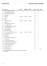
Страница 145: ...Spare Parts and Schematics Basic Printer 7 5 Basic Printer 2 3 462646...
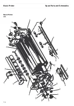
Страница 146: ...Basic Printer Spare Parts and Schematics 7 6 Basic Printer 3 3...
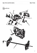
Страница 147: ...Spare Parts and Schematics Basic Printer 7 7 7 2 2 Carriage RMS and Platen 72 125 138 139 136 62 11 137...
Страница 151: ...This page intentionally left blank...
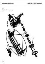
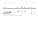
Страница 152: ...Standard Tractor Assy Spare Parts and Schematics 7 12 7 3 Standard Tractor Assy 462646 134 140 17...
Страница 162: ...PMS Double Sensor Spare Parts and Schematics 7 22 7 8 PMS Double Sensor T R T R T Transmit R Receive...
Страница 164: ...Option Recognition Spare Parts and Schematics 7 24 7 10 Option Recognition...
Страница 168: ...This page intentionally left blank...
Страница 170: ...Tractor Complete Rear Tractor 2T Model 8 2 8 2 Tractor Complete 4 1...
Страница 172: ...This page intentionally left blank...
Страница 174: ...Cutting Device Option Specifications 9 2 14 6 4 12 1 5 6 11 7 13 7 8 17 2 9 3 16 15 4...
Страница 176: ...This page intentionally left blank...
Страница 177: ...2nd Front Tractor option 10 1 10 2nd Front Tractor option...
Страница 179: ...Printer Stand Overview 11 1 11 Printer Stand 11 1 Overview...
Страница 180: ...Installing the Printer Stand Printer Stand 11 2 11 2 Installing the Printer Stand 1 2 3 4...
Страница 181: ...Printer Stand Installing the Printer Stand 11 3 6 8 7 5...
Страница 182: ...Installing the Printer Stand Printer Stand 11 4 9 10...

