background image

Copyright TEL

31/01/96

T830 Series

Base Station Equipment

Service Manual

Issue 100

February 1996

M830-00-100

Содержание T830 Series

Страница 1: ...Copyright TEL 31 01 96 T830 Series Base Station Equipment Service Manual Issue 100 February 1996 M830 00 100...

Страница 2: ...72 5300 France Tait France Sarl 2 Avenue de la Cristallerie 92 316 S vres Cedex France Phone 33 1 41 14 05 50 Fax 33 1 41 14 05 55 Germany Tait Mobilfunk GmbH Willst tterstra e 50 D 90449 N rnberg 60...

Страница 3: ...Quality Standards but will also serve to identify which pages have been updated and when Each page and its publication date is listed in the List of Effective Pages and a new list containing any new r...

Страница 4: ...addressed in the first instance to your nearest approved Tait Dealer or Service Centre Further technical assistance may be obtained from the Customer Support Group Radio Infra structure Division Tait...

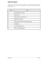
Страница 5: ...er sub divided into sections There is a detailed table of contents at the start of each part and or section Part Title A Introduction To Servicing B T835 Receiver C T836 Transmitter T837 Exciter D T83...

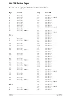
Страница 6: ...1 31 01 96 7 2 31 01 96 8 1 31 01 96 8 2 31 01 96 blank Part B I 31 01 96 II 31 01 96 blank 1 1 31 01 96 1 2 31 01 96 blank 1 3 31 01 96 1 4 31 01 96 1 5 31 01 96 1 6 31 01 96 1 7 31 01 96 1 8 31 01 9...

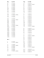
Страница 7: ...96 blank 1 1 31 01 96 1 2 31 01 96 blank 1 3 31 01 96 1 4 31 01 96 1 5 31 01 96 1 6 31 01 96 1 7 31 01 96 1 8 31 01 96 blank 2 1 31 01 96 2 2 31 01 96 blank 2 3 31 01 96 2 4 31 01 96 2 5 31 01 96 2 6...

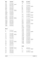
Страница 8: ...6 2 5 31 01 96 2 6 31 01 96 3 1 31 01 96 3 2 31 01 96 blank 3 3 31 01 96 3 4 31 01 96 3 5 31 01 96 3 6 31 01 96 3 7 31 01 96 3 8 31 01 96 4 1 31 01 96 4 2 31 01 96 blank 4 3 31 01 96 4 4 31 01 96 4 5...

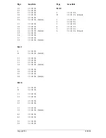
Страница 9: ...31 01 96 blank Part F I 31 01 96 II 31 01 96 blank 1 1 31 01 96 1 2 31 01 96 1 3 31 01 96 1 4 31 01 96 blank 2 1 31 01 96 2 2 31 01 96 2 3 31 01 96 2 4 31 01 96 blank Part G I 31 01 96 II 31 01 96 1 1...

Страница 10: ...31 01 96 Copyright TEL...

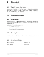
Страница 11: ...rs 1 1 1 1 1 2 1 2 2 2 1 2 2 2 2 1 2 2 2 2 3 Mechanical Pozidriv Recess Head Screws Disassembly Reassembly Receivers Exciters Power Amplifiers Cover Screw Torques 2 1 2 1 2 1 2 1 2 1 2 1 3 3 1 3 1 1 3...

Страница 12: ...31 01 96 Copyright TEL...

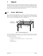
Страница 13: ...from static charges Care when handling these devices is essential For correct handling proce dures refer to the manufacturers data books e g Philips data books covering CMOS devices or Motorola CMOS d...

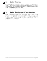
Страница 14: ...is warning may result in damage to the transmitter output power stage 1 3 Caution Beryllium Oxide Power Transistors The RF power transistors in current use all contain some beryllium oxide This sub st...

Страница 15: ...ters To carry out alignment or change option links it is necessary to remove only the top cover i e the one adjacent to the front panel handle and on the opposite side to the main D range connector Re...

Страница 16: ...31 01 96 Copyright TEL...

Страница 17: ...en com pleted Remove the tip while continuing suction to ensure that all solder is removed from the joint then stop the suction Before pulling the lead out ensure it is not stuck to the plating If the...

Страница 18: ...replacement techniques This equipment should be serv iced only by an approved Tait Dealer or Service Centre equipped with the necessary facilities Repairs attempted with incorrect equipment or by untr...

Страница 19: ...me procedure applies for the SOE stud package Caution Do not solder the tabs before torquing down otherwise the device may be broken Desolder the tabs by heating with a soldering iron and lifting away...

Страница 20: ...31 01 96 Copyright TEL...

Страница 21: ...the front panel Remove the mounting screw for the TO 220 device Q5 Remove the output 50 ohm coaxial connector by unscrewing it from the heatsink casting and unsoldering it from the PCB Disconnect the...

Страница 22: ...31 01 96 Copyright TEL...

Страница 23: ...1 96 6 To Remove Cased Mica Capacitors Cased mica capacitors can be removed by heating the top with a heavy duty soldering iron and gently lifting the capacitor off the PCB with a solder resistant spi...

Страница 24: ...31 01 96 Copyright TEL...

Страница 25: ...ay adaptors Programming of CTCSS frequency data optional for individual channels Full cursor control in edit mode User selectable output file format hex or binary Support for wider range of T800 equip...

Страница 26: ...d below Includes several new radio models which are not programmable with PGM800 V2 01 Default file names with dash are saved with dash instead of underscore Default file extension in Save File page i...

Страница 27: ...u may wish to file a copy of each TI in this Section for your own reference TI No Title Date 346D 356C 358 365 373A 403 416B 418 422 T800 02 CTCSS encoder decoder T800 07 multichannel memory PCB T807...

Страница 28: ...31 01 96 Copyright TEL...

Страница 29: ...e manual is divided into six sections as listed below There is a detailed table of contents at the start of each section Section Title 1 General Information 2 Circuit Operation 3 Initial Tuning Adjust...

Страница 30: ...31 01 96 Copyright TEL...

Страница 31: ...T835 receiver along with detailed speci fications and a list of variants available The following topics are covered in this section Section Title Page 1 1 Introduction 1 3 1 2 1 2 1 1 2 2 1 2 3 1 2 4...

Страница 32: ...31 01 96 Copyright TEL...

Страница 33: ...r de emphasised audio response is link selectable The synthesiser frequency is programmed via an EPROM which is attached to a sepa rate plug in memory board A DIP switch on the memory PCB allows fast...

Страница 34: ...ion is given Details of test methods and the conditions which apply for Type Approval testing in all countries can be obtained from Tait Electronics Ltd 1 2 2 General Frequency Range 136 174MHz Type d...

Страница 35: ...12dB Sinad 115dBm Signal Noise To Noise Ratio RF Level 107dBm 30dB RF Level 83dBm NB 50dB CEPT typical RF Level 57dBm WB 55dB EIA typical Selectivity Narrow Band 12 5kHz 88dB CEPT typical Wide Band 25...

Страница 36: ...ve de emphasis characteristic ref 1kHz Line Output Power adjustable to 10dBm Load Impedance 600 ohms Distortion 70dBm signal level links set to de emphasis Narrow Band 4 Wide Band 2 Monitor Output Pow...

Страница 37: ...of 1ppm 0 C to 60 C is available to suit specific requirements Contact your nearest authorised Tait Dealer or Service Centre for further details Description Version 10 15 20 25 136 156MHz 148 174MHz...

Страница 38: ...31 01 96 Copyright TEL...

Страница 39: ...2 5 2 4 IF Circuitry 2 5 2 5 Noise Mute Squelch 2 6 2 6 Carrier Mute 2 6 2 7 Audio Processor 2 7 2 8 Power Supply And Regulator 2 8 2 9 Synthesised Local Oscillator 2 9 2 10 Received Signal Strength...

Страница 40: ...31 01 96 Copyright TEL...

Страница 41: ...mute squelch regulator circuits received signal strength indicator RSSI These stages are clearly identifiable in Figure 2 1 Refer to the circuit diagrams at the rear of the Manual for further detail 2...

Страница 42: ...the mixer Each sub block within the front end has been designed with 50 ohm terminations for ease of testing and fault finding The overall gain from the antenna socket to the mixer input varies from 0...

Страница 43: ...xer amplifier Q303 Several stages of amplification and filtering are employed in the IF circuitry The first crystal filter is a 4 pole device XF301 which is matched into 50 ohms on both its input and...

Страница 44: ...bled for test purposes by operating the front panel mute disable switch SW100 The mute control line is available on pad 101 Rx gate out for control of external cir cuitry A high 9V on pad 101 indicate...

Страница 45: ...t panel volume knob RV103 and the line level is set using the recessed potentiometer RV102 The signals are passed to audio drive amplifiers IC102 and IC103 Under muted conditions the inputs of these a...

Страница 46: ...used as the reference for a DC amplifier IC201 Q200 Q201 which provides a medium current capability 9V supply A switching power supply based on Q202 and Q203 runs off the 9V supply and provides a low...

Страница 47: ...vider is stored within EPROM memory IC1 Up to 128 frequencies can be stored within the memory and are addressable using the internal DIP switches Three of the address lines are also available for exte...

Страница 48: ...VCO frequency spans from either 157 177MHz or 169 196MHz according to ver sion The VCO is tuned to 21 4MHz above the desired receive frequency to produce a 21 4MHz IF signal on the output of the mixer...

Страница 49: ...on Title Page 3 1 Channel Programming 3 3 3 2 DIP Switch Codes For Channel Addresses 3 3 3 3 3 3 1 3 3 2 Audio Processor Links General Audio Processor Linking Details For CTCSS 3 4 3 4 3 5 3 4 Test Eq...

Страница 50: ...31 01 96 Copyright TEL Figure Title Page 3 1 3 2 Channel DIP Switch Setting Test Equipment Set up 3 3 3 6...

Страница 51: ...hile the most significant bit 8 is selected according to the EPROM used refer to Section 3 1 This will allow the existing CHSEL lines to be used to select up to 8 channels It is possible to address bl...

Страница 52: ...f the receiver is attempted Plug Link Function PL100 1 2 2 3 Rx disable link not connected PL101 1 2 2 3 flat response de emphasised response PL102 1 2 2 3 relay link not connected PL103 1 2 2 3 de em...

Страница 53: ...and speech transmitted down 600 ohm line line output audio bandwidth 10Hz to 3kHz hum noise 45dB decoding performed in exciter transmitter internal CTCSS decoding performed in receiver by T800 02 or...

Страница 54: ...r to PL4 1 or the junction of L1 R1 in the VCO this measures the synthesiser loop voltage Single Channel Tune VCO trimmer VC1 for a synthesiser loop voltage of 9V Multichannel Tune VCO trimmer VC1 for...

Страница 55: ...RF input to the receiver loosely cou ple into the first IF an additional high level signal at 21 4MHz a beat note will be heard Trim the synthesiser TCXO IC2 for zero beat Readjust the front end doubl...

Страница 56: ...he front panel may be adjusted for the required opening sinad 3 8 Audio Processor 3 8 1 Line Amplifier Output Apply an on channel signal from the RF generator at a level of 70dBm with 3kHz deviation 1...

Страница 57: ...e connector when measured with a high impedance DMM 3 10 Carrier Level Mute Connect pins 2 and 3 of PL104 to enable the carrier mute and disable the noise mute Apply an on channel signal from the RF g...

Страница 58: ...0 channel numbers can range from 0 127 or 1 128 depending on which version you are using The following sections provide DIP switch code lists for both numbering systems Version Channel Numbers V2 and...

Страница 59: ...1100 52 X1001011 53 X1001010 54 X1001001 55 X1001000 56 X1000111 57 X1000110 58 X1000101 59 X1000100 60 X1000011 61 X1000010 62 X1000001 63 X1000000 64 X0111111 65 X0111110 66 X0111101 67 X0111100 68...

Страница 60: ...1100 53 X1001011 54 X1001010 55 X1001001 56 X1001000 57 X1000111 58 X1000110 59 X1000101 60 X1000100 61 X1000011 62 X1000010 63 X1000001 64 X1000000 65 X0111111 66 X0111110 67 X0111101 68 X0111100 69...

Страница 61: ...s for narrow band sets The following topics are covered in this section Section Title Page 4 1 Current Consumption 4 3 4 2 Sensitivity 4 3 4 3 Switching Band Multichannel Only 4 3 4 4 Audio Distortion...

Страница 62: ...31 01 96 Copyright TEL...

Страница 63: ...control to give maximum outputs Check that the current is less than 750mA 4 2 Sensitivity Apply an on channel signal from the RF generator with 3kHz deviation 1 5kHz at 1kHz Adjust the RF level to gi...

Страница 64: ...olume control RV103 to give 2V rms into a 4 ohm resistive load Check that the distortion at the monitor output is better than 2 THD 4 5 Ultimate Signal To Noise Ratio Apply a signal from the RF genera...

Страница 65: ...losely follows that shown in Figure 4 1 the limits should not be exceeded Note The curve is shown for wide band sets The narrow band response is simi lar but rolls off earlier at 2 5kHz Figure 4 1 De...

Страница 66: ...the mute opens Reset the mute pot to give the required opening sinad 4 8 RSSI Apply an on channel signal from the RF generator at a level of 100dBm with 3kHz deviation 1 5kHz at 1kHz Using a high impe...

Страница 67: ...In Apply an on channel signal from the RF generator at a level of 120dBm with 3kHz deviation 1 5kHz at 1kHz Increase the RF level in 2dB steps and check that the mute opens at an RF level which corres...

Страница 68: ...31 01 96 Copyright TEL...

Страница 69: ...d Christchurch New Zealand The following topics are covered in this section Section Title Page 5 1 Visual Checks 5 3 5 2 Component Checks 5 3 5 3 5 3 1 5 3 2 5 3 3 DC Checks Power Rails VCO Locking Mu...

Страница 70: ...31 01 96 Copyright TEL...

Страница 71: ...First make sure that the transistor is not shunted by some circuit resistance unless the device is completely desoldered A 20k ohm V or better multimeter should be used for taking the measurements usi...

Страница 72: ...tor the VCO control voltage at PL4 1 or the junction of L1 R1 located adjacent to the electrolytic capacitor on the VCO PCB If the synthesiser is locked and the VCO aligned the voltage at this point s...

Страница 73: ...essive circuit blocks Prepare a test cable by connecting a 1nF capacitor to the end of a length of coax cable as shown in Figure 5 1 Figure 5 1 RF Test Cable Note Before using the test cable ensure th...

Страница 74: ...essary 5 4 4 Demodulator Output Apply an on channel RF signal modulated by 1kHz with 3kHz 1 5kHz deviation at an amplitude of 65dBm Connect an oscilloscope probe DC coupled to IC303 pin 7 audio output...

Страница 75: ...IF Swept Response Increase the RF level to 50dBm the trace will now show the shape of the 455kHz ceramic filter XF303 Check that the response has no sharp non linearities If sharp non linearities do o...

Страница 76: ...TP1 13 8V TP2 9V TP3 20V TP4 5V 5 5 1 Regulator Check for overheating components short circuits 13 8V present on IC202 pin 3 5 3V present on IC202 pin 1 9 0V present on TP2 20V present on TP3 Check co...

Страница 77: ...ing resistors Q1 N N N N N Y Y Y Y Y N N N N N N N N N Y Y Y Y Y Y Y Y Y Y Y Y N Y Y VCO trimmer freq range OK VCO OK Does IC3 pin 1 PDA change level at the programmed synth freq Does control line O P...

Страница 78: ...e transition on IC3 pin 14 for 3 LSB DIP switch operation if wrong check C15 C16 C2 C4 C6 on EPROM PCB Check presence of low level on IC3 pin 14 for 200ms on switch on change IC3 Provide new EPROM Go...

Страница 79: ...r voltage on IC100 pin 7 Switching 0 8V as pot rotated Monitor voltage on pad 101 Switching 0 8V as pot rotated Does LED toggle Refer to Rx fault finding chart Check components around active filter Ch...

Страница 80: ...oltage varies 0 6V N Check 9V rail resistors R154 R156 RV104 Monitor voltage on IC100 pin 7 Switching 0 8V as pot rotated Monitor voltage on pad 101 Switching 0 8V as pot rotated Does LED toggle Check...

Страница 81: ...stortion Check sensitivity into each stage see 5 4 2 Check repair faulty stage or component Replace faulty device See Chart B below Y N N Y A Poor sensitivity worse than 117dBm Quad coil L319 tuned fo...

Страница 82: ...Ensure mute pot fully clockwise Mute LED on Refer to mute fault finding chart Refer to mute fault finding chart Audio on C115 C116 Audio on IC102 pin 2 IC103 pin 2 Replace faulty device Audio on spea...

Страница 83: ...ides parts lists a grid reference index PCB layouts test points and options draw ings and circuit diagrams for the T835 receiver This section contains the following information Section Title IPN Page...

Страница 84: ...31 01 96 Copyright TEL...

Страница 85: ...handled more efficiently if you quote the IPN and provide a brief descrip tion of the part The components listed in this parts list are divided into two main types those with a circuit refer ence e g...

Страница 86: ...seful in following a circuit that is spread over two or more sheets When a line representing part of the circuitry is discontinued a reference will be given at the end of the line to indicate where th...

Страница 87: ...hanical Miscellaneous Parts Grid Reference Index PCB Layout Top Side PCB Layout Bottom Side Test Points Options Top Side Test Points Options Bottom Side Synthesiser Circuit Diagram Audio Processor Cir...

Страница 88: ...31 01 96 Copyright TEL...

Страница 89: ...117 020 59100 06 CAP ELECT AI RDL 100M 16V 6 3X11MM C118 020 59100 06 CAP ELECT AI RDL 100M 16V 6 3X11MM C119 015 24100 08 CAP CER 0805 CHIP 1N 10 X7R 50V C120 015 24100 08 CAP CER 0805 CHIP 1N 10 X7R...

Страница 90: ...50V C388 015 05470 08 CAP CER 1206 CHIP 47N 10 X7R 50V C500 10 015 20050 01 CAP CER 0805 CHIP 0P5 0 5P NPO 50 C500 15 015 22100 01 CAP CER 0805 CHIP 10P 0 5P NPO 50 C500 20 015 20050 01 CAP CER 0805...

Страница 91: ...25 036 14330 00 RES M F 0805 CHIP 3K3 5 R153 036 15100 00 RES M F 0805 CHIP 10K 5 R154 036 13100 00 RES M F 0805 CHIP 100E 5 R155 036 15150 00 RES M F 0805 CHIP 15K 5 R156 036 14560 00 RES M F 0805 C...

Страница 92: ...6 50 COIL TAIT NO 650 455KHZ 5 6MM CAN VC301 028 02100 06 CAP TRIM 3 10P NPO TOP ADJ BLUE MUR TZ X301 274 00010 02 XTAL 20 945MHZ SPEC TE 15 C W TEFLON IN XF301 10 276 00010 43 FLTR XTAL HY Q 1PR 21 4...

Страница 93: ...D RANGE SKT BOX 316 85100 00 PLATE FRT A2M2249 DUAL D RANGE SKT BOX 318 01014 00 RAIL A2M2214 FOR 800 SERIES FXD EQUIP 319 01152 00 SHIELD A3M2250 F THRU MTG T857 345 00040 06 SCREW M3 8MM PAN POZI ST...

Страница 94: ...31 01 96 Copyright TEL...

Страница 95: ...C215 1 R9 3 E8 C216 2 S7 3 H1 C217 2 S6 3 J2 C218 2 T9 3 K3 C219 2 R7 3 N6 C220 2 R8 3 G6 C221 2 R6 3 M6 C222 2 R9 3 F8 C301 2 V9 4 B7 C302 2 V9 4 B7 C303 2 V10 4 C7 C304 2 V11 4 C7 C305 2 T11 4 D7 C3...

Страница 96: ...R30 2 P5 1 J5 R31 2 P5 1 K6 R32 2 N5 1 M4 R33 2 N5 1 M2 R34 2 N4 1 L5 R35 2 N5 1 N4 R36 2 P8 1 M5 R37 2 S4 1 Q8 R38 2 T4 1 C7 R39 2 S4 1 D8 R40 2 T3 1 E9 R41 2 L5 1 B5 R42 2 M4 1 D6 R43 2 K5 1 B4 R44...

Страница 97: ...V8 4 A7 R365 2 H12 4 E4 R366 2 H8 4 L4 R367 1 G10 4 M2 R368 2 G10 4 M1 R369 2 G5 4 G0 R370 2 G11 4 F3 R371 2 H11 4 G4 R372 2 G11 4 G3 R373 2 L8 1 A4 RL100 1 D2 2 K1 2 N1 2 N0 SJ2 1 L8 1 A4 SJ3 1 L7 1...

Страница 98: ...31 01 96 Copyright TEL...

Страница 99: ...M830 00 T835 PCB Information B6 2 13 Copyright TEL 31 01 96 T835 PCB Layout Top Side 220 01186 02...

Страница 100: ...B6 2 14 T835 PCB Information M830 00 31 01 96 Copyright TEL T835 PCB Layout Bottom Side 220 01186 02...

Страница 101: ...M830 00 T835 PCB Information B6 2 15 Copyright TEL 31 01 96 T835 Test Points Options Top Side 220 01186 02...

Страница 102: ...B6 2 16 T835 PCB Information M830 00 31 01 96 Copyright TEL T835 Test Points Options Bottom Side 220 01186 02...

Страница 103: ...M830 00 T835 PCB Information B6 2 17 Copyright TEL 31 01 96 Sheet 1 T835 Synthesiser 220 01186 02...

Страница 104: ...B6 2 18 T835 PCB Information M830 00 31 01 96 Copyright TEL 6K8S 3K9S Sheet 2 T835 Audio Processor 220 01186 02...

Страница 105: ...M830 00 T835 PCB Information B6 2 19 Copyright TEL 31 01 96 Sheet 3 T835 Regulator 220 01186 02...

Страница 106: ...B6 2 20 T835 PCB Information M830 00 31 01 96 Copyright TEL 8K2S Sheet 4 T835 Receiver 220 01186 02...

Страница 107: ...rt of the manual is divided into six sections as listed below There is a detailed table of contents at the start of each section Section Title 1 General Information 2 Circuit Operation 3 Initial Tunin...

Страница 108: ...31 01 96 Copyright TEL...

Страница 109: ...nsmitter and T837 exciter along with detailed specifications and a list of variants available The following topics are covered in this section Section Title Page 1 1 Introduction 1 3 1 2 1 2 1 1 2 2 1...

Страница 110: ...31 01 96 Copyright TEL...

Страница 111: ...e band output amplifier The synthesiser frequency is programmed via an EPROM which is attached to a sepa rate plug in memory PCB A DIP switch on the memory PCB allows fast single channel selection fro...

Страница 112: ...methods and the conditions which apply for Type Approval testing in all countries can be obtained from Tait Electronics Ltd 1 2 2 General Frequency Range 136 174MHz refer to Section 1 3 Modulation Ty...

Страница 113: ...Section Adjacent Channel Power full deviation Wide Band 25kHz 15kHz B W 75dBc Narrow Band 12 5kHz 7 5kHz B W 65dBc Transmitter Side Band Noise no modulation 15kHz bandwidth At 25kHz 95dBc At 1MHz 105...

Страница 114: ...cy Response flat or pre emphasised optional below limiting Line And Microphone Inputs Pre emphasised Response Bandwidth 300Hz to 3kHz Below Limiting within 1 3dB of a 6dB octave pre emphasis character...

Страница 115: ...lity of 1ppm 0 C to 60 C is available to suit specific requirements Contact your nearest authorised Tait Dealer or Service Centre for further details Description Version 10 15 20 25 136 156MHz 148 174...

Страница 116: ...31 01 96 Copyright TEL...

Страница 117: ...O Supply 2 6 2 6 2 6 2 4 2 4 1 2 4 2 2 4 3 2 4 4 2 4 5 Audio Processor General Audio Inputs Keying Inputs Compressor Outputs To Modulators 2 7 2 7 2 7 2 8 2 8 2 8 2 5 Power Supply Regulator Circuits 2...

Страница 118: ...31 01 96 Copyright TEL...

Страница 119: ...on a functional level in Figure 2 1 and Figure 2 2 Refer to the circuit diagrams for more detail Figure 2 1 T836 High Level Block Diagram Figure 2 2 T837 High Level Block Diagram Audio Processor Synth...

Страница 120: ...e phase detector outputs are passed through an active loop filter IC6 which produces a DC voltage between 0V and 20V to tune the VCO This VCO control line is further filtered to attenuate noise and ot...

Страница 121: ...erence Oscillator Fixed Divider Phase Modulator Reference Divider Phase Detector Loop Filter VCO PCB VCO Modulation VCO Buffer Output Buffer 22dBm L O Programmable Divider VHF Prescaler Divider Buffer...

Страница 122: ...e input to Q5 and used to drive the divider buffer for the VHF prescaler IC3 The prescaler divide ratio is 40 41 The VCO operates at the actual output frequency of the exciter i e there are no multi p...

Страница 123: ...ed line and the other from a local microphone The microphone signal is passed first to a pre amplifier Q101 and ultimately to a multiplexer IC101 but in between may pass through the compressor dependi...

Страница 124: ...l This square wave pumps up the reservoir capacitor C129 which controls the attenuator Q103 Q104 thus complet ing the feedback loop The compression level is set by adjustment of the comparator thresho...

Страница 125: ...ply the synthesiser loop filter IC6 giving a VCO control voltage range of up to 20V Ultimate control of the transmitter is via the Tx reg supply switched from 9V by Q211 This is enabled by the Tx enab...

Страница 126: ...en to the final Q424 DC is fed to the final via a low pass filter with special low frequency decou pling CV400 tunes the output matching across the entire band The directional coupler provides the req...

Страница 127: ...hannel Programming 3 3 3 2 DIP Switch Codes For Channel Addresses 3 3 3 3 3 3 1 3 3 2 Audio Processor Links Link Details Typical Options 3 4 3 4 3 4 3 4 Test Equipment Set up 3 5 3 5 Synthesiser Align...

Страница 128: ...2 PGM800 DIP Switch Codes DIP Switch Codes For Channel Numbers 0 127 DIP Switch Codes For Channel Numbers 1 128 3 11 3 12 3 13 Figure Title Page 3 1 3 2 Channel DIP Switch Setting T836 837 Test Equipm...

Страница 129: ...while the most significant bit 8 is selected according to the EPROM used refer to Section 3 1 This will allow the existing CHSEL lines to be used to select up to 8 channels It is possible to address b...

Страница 130: ...nput PL102 1 2 3 4 5 6 7 8 9 10 not connected not connected compressor output to pre emphasis input compressor output to limiter input compressor output to multiplexer input PL103 1 2 3 4 5 6 pre emph...

Страница 131: ...igure 3 2 T836 837 Test Equipment Set up Frequency Counter Audio Generator Line I P CTCSS I P 600 Audio Voltmeter Audio Voltmeter RF Power Meter Oscilloscope AF O P Modulation Meter Key RF O P Exciter...

Страница 132: ...ultichannel Tune VCO trimmer VC1 for a synthesiser loop voltage of 9V on the middle channel If there is no middle channel tune VC1 so that the chan nels are symmetrically placed around a loop voltage...

Страница 133: ...obtained Reduce the current by approximately 1A by detuning CV400 or until the power drops below 30W Check that the total current drawn is less than 4 5A for 25W output power Adjust RV356 for an outpu...

Страница 134: ...ignal of 600Hz 1 5V rms 5dBm into the CTCSS input D range pin 8 Earth the key line 2 Adjust the output from the audio generator to obtain 3kHz 1 5kHz deviation at 600Hz 3 Change the input frequency to...

Страница 135: ...provide 3kHz 1 5kHz deviation 3 8 5 Compressor The compressor may be used on the line input only the microphone input only or on both the line and microphone inputs If the compressor is used refer to...

Страница 136: ...nticlockwise until the demodulated waveform is just clipping approximately 4kHz 2kHz deviation Increase the audio level by 10dB and verify that the test tone is held just into clip ping Whistle steadi...

Страница 137: ...0 channel numbers can range from 0 127 or 1 128 depending on which version you are using The following sections provide DIP switch code lists for both numbering systems Version Channel Numbers V2 and...

Страница 138: ...100 52 X1001011 53 X1001010 54 X1001001 55 X1001000 56 X1000111 57 X1000110 58 X1000101 59 X1000100 60 X1000011 61 X1000010 62 X1000001 63 X1000000 64 X0111111 65 X0111110 66 X0111101 67 X0111100 68 X...

Страница 139: ...100 53 X1001011 54 X1001010 55 X1001001 56 X1001000 57 X1000111 58 X1000110 59 X1000101 60 X1000100 61 X1000011 62 X1000010 63 X1000001 64 X1000000 65 X0111111 66 X0111110 67 X0111101 68 X0111100 69 X...

Страница 140: ...31 01 96 Copyright TEL...

Страница 141: ...ctions deviation settings are given first for wide band sets followed by settings in brackets for narrow band sets The following topics are covered in this section Section Title Page 4 1 Current Consu...

Страница 142: ...31 01 96 Copyright TEL...

Страница 143: ...utput Power Connect an RF power meter to the T836 837 output socket Key the T836 837 Check that T836 the output power adjusts to 30W with RV356 turned fully clockwise T837 the output power is 800mW 20...

Страница 144: ...transmit time 4 6 Frequency Response If the T836 837 has been correctly adjusted the pre emphasis and limiting responses should closely match those shown in Figure 4 1 and Figure 4 2 respectively Not...

Страница 145: ...4 2 0 2 4 6 8 10 12 14 16 20 22 100 200 300 500 1k 2k 3k 5k 10k Frequency Hz Peak max dev 1 0kHz 1000Hz Peak max dev 1 0kHz 1000Hz 100 500 300 5k 50 10 8 Modulation Level dB ref to max dev 6 4 2 0 2 4...

Страница 146: ...raded signal to noise ratio can be expected with the compressor selected The extent of the degradation is dependent on the audio input level Line Input 600 ohms 3kHz 1 5kHz deviation at 1kHz with comp...

Страница 147: ...omer Support Group Radio Infrastructure Division Tait Elec tronics Ltd Christchurch New Zealand The following topics are covered in this section Section Title Page 5 1 Visual Checks 5 3 5 2 Component...

Страница 148: ...31 01 96 Copyright TEL...

Страница 149: ...s First make sure that the transistor is not shunted by some circuit resistance unless the device is completely desoldered A 20k ohm V or better multimeter should be used for taking the measurements u...

Страница 150: ...xciter comes up to 8 8V when the exciter is keyed Check for short circuits 5 3 2 VCO Locking Key the exciter Using a DMM monitor the VCO control voltage at the junction of L1 and R1 on the VCO PCB If...

Страница 151: ...synthesiser is out of lock by switching the supply to the exciter amplifier Q300 Q301 5 4 2 T836 PA Output Power Reconnect the drive output to the PA input Connect the PA to a power meter and key the...

Страница 152: ...audio processor as described in Section 3 8 Check that the demodulated RF output has the frequency response referred to in Section 4 6 with at least 5kHz 2 5kHz deviation available at 1kHz modulating...

Страница 153: ...09 IC202d 20V present on TP3 N Check Q208 is switching at approx 150kHz Key Tx 8 8V present on Tx reg TP5 Regulators OK 0V present on IC202 pin 8 Replace Q211 IC202 pin 9 2 5V Check IC202c associated...

Страница 154: ...ne O P level change on IC6 pin 1 Check loop filter cct around IC6 9V reg present at VCO amp Q4 Q5 Check Tx reg Q211 9V reg N Y DC V present at Q4 Q5 Check biasing resistors Q4 Q5 N Y 8 3V present at V...

Страница 155: ...IC5 on 3 address 4 data lines Check for edge transition on IC5 pin 14 for 3 LSB DIP switch operation if wrong check C17 C19 C2 C4 C6 on EPROM PCB Change IC5 Replace IC5 synthesiser OK Go to B Correct...

Страница 156: ...a pin 1 3 5V on Q300 collector 10 5V on Q301 collector 0 4V on Q304 base Key exciter lock synthesiser Check lock det path back to synth IC5 Check C335 C317 C364 Q300 Check temp shutdown circuit Does R...

Страница 157: ...ower sense circuitry directional coupler D410 D411 circuitry Check lock det circuit Q350 base should be 0V Temp shutdown circuit IC350 pin 7 should be 0V Check Q353 Check RV356 divider chain Set RV356...

Страница 158: ...2 11V present on IC350a pin 1 N N Y Check VCO N 2 2V RF at R300 R301 Y N Y 1 1V RF at R301 R302 Check attenuator pad R300 R301 R302 0 5V RF at Q300 base Check C335 L300 L311 Q300 N Key exciter lock sy...

Страница 159: ...y exciter lock synthesiser Connect 1kHz audio to CTCSS input N Y Y Y Y N N N Y N Y Y Y Y N N N N N Y N Y Y N N N N N Y Y Y Y Audio superimposed on 200kHz signal IC7 pins 9 13 synth 200kHz clipped tria...

Страница 160: ...31 01 96 Copyright TEL...

Страница 161: ...a common main PCB with the T836 having the additional compo nents fitted to the PA section of the board While we have provided individual parts lists for each product all other information provided i...

Страница 162: ...31 01 96 Copyright TEL...

Страница 163: ...handled more efficiently if you quote the IPN and provide a brief descrip tion of the part The components listed in this parts list are divided into two main types those with a circuit refer ence e g...

Страница 164: ...seful in following a circuit that is spread over two or more sheets When a line representing part of the circuitry is discontinued a reference will be given at the end of the line to indicate where th...

Страница 165: ...Parts T837 Parts List T837 Mechanical Miscellaneous Parts Grid Reference Index PCB Layout Top Side PCB Layout Bottom Side Test Points Options Top Side Test Points Options Bottom Side Synthesiser Circ...

Страница 166: ...31 01 96 Copyright TEL...

Страница 167: ...CAP ELECT RADL 22M 16V 5X11MM Note With the exception of the following components R425 R426 R427 R428 R367 the character is used in the exciter PA circuit dia gram and this Parts List to indicate comp...

Страница 168: ...002 00020 50 S IC 4N25A OPTOCOUPLER IC101 002 00015 30 S IC 4053B 2CHAN MUX DEMUX IC102 002 00014 40 S IC 324 QUAD OP AMP IC103 002 00012 25 S IC TL084 QUAD OP AMP JFET I P IC104 002 00012 40 S IC 358...

Страница 169: ...P 56K 5 R186 036 15100 00 RES M F 0805 CHIP 10K 5 R187 036 15560 00 RES M F 0805 CHIP 56K 5 R188 036 17100 00 RES M F 0805 CHIP 1M 5 R189 036 13560 00 RES M F 0805 CHIP 560E 5 R190 036 14220 00 RES M...

Страница 170: ...NTRY SK100 240 02020 05 SKT STEREO PHONE JACK PCB MTG SK300 240 02100 44 SKT COAX MINI JACK PCB MTG ANGLED SK401 240 02100 44 SKT COAX MINI JACK PCB MTG ANGLED SW101 232 00010 26 SWITCH PUSH SPDT RT A...

Страница 171: ...100 00 PLATE FRT A2M2249 DUAL D RANGE SKT BOX 318 01014 00 RAIL A2M2214 FOR 800 SERIES FXD EQUIP 319 01152 00 SHIELD A3M2250 F THRU MTG T857 345 00040 06 SCREW M3 8MM PAN POZI ST BZ skt box x2 345 000...

Страница 172: ...31 01 96 Copyright TEL...

Страница 173: ...8 CAP CER 0805 CHIP 10N 10 X7R 50V Note The character is used in this Parts List to indicate components used only in the T837 R367 or those components common to both T836 and T837 but with different v...

Страница 174: ...L SIG Q101 000 10008 48 S XSTR SMD BCW60 BC848B215 NPN SOT23 Q102 000 10008 57 S XSTR SMD BCW70 PNP SOT23 AF SML SIG Q103 000 10008 17 S XSTR SMD BC817 25 NPN SOT 23 AF LO Q104 000 10008 48 S XSTR SMD...

Страница 175: ...0 RES M F PWR 1E0 5 1W 12X4 5MM R235 036 14680 00 RES M F 0805 CHIP 6K8 5 R236 036 15100 00 RES M F 0805 CHIP 10K 5 R237 036 15100 00 RES M F 0805 CHIP 10K 5 R238 036 16100 00 RES M F 0805 CHIP 100K 5...

Страница 176: ...URE T306 316 85015 01 PIN A4M775 LOCATING D RANGE 316 85099 00 PLATE FLOAT A2M2248 DUAL D RANGE SKT BOX 316 85100 00 PLATE FRT A2M2249 DUAL D RANGE SKT BOX 318 01014 00 RAIL A2M2214 FOR 800 SERIES FXD...

Страница 177: ...3 C2 C216 2 T6 3 C3 C217 2 V5 3 C5 C218 2 S7 3 H1 C219 1 T8 3 F3 C220 2 T8 3 F3 C221 2 T8 3 F3 C222 1 S7 3 J3 C223 1 R8 3 N1 C224 1 R7 3 L6 C225 2 R7 3 N6 C226 1 R8 3 N6 C227 1 R9 3 Q7 C228 2 R6 3 D3...

Страница 178: ...1 K8 R62 2 Q3 1 K7 R64 2 Q4 1 C7 R65 2 S4 1 D7 R67 2 S3 1 G7 R68 2 S4 1 G7 R72 2 P8 1 N5 R73 2 P8 1 N5 R74 2 L5 1 B5 R75 2 M5 1 E5 RV100 1 B9 2 B4 R100 2 C4 2 B0 R101 2 D4 2 B1 R102 2 D4 2 C1 R103 2...

Страница 179: ...4 G3 R462 0 B1 4 G1 R464 0 B1 4 G2 R466 2 S12 4 L1 R469 2 S12 4 M3 R470 2 S11 4 M2 R471 2 U11 4 N1 R480 2 U12 4 N3 R481 2 T10 4 M1 R482 1 N12 4 A6 SK1 1 K5 1 B1 1 B3 1 B3 1 B3 1 B2 1 B2 1 B2 1 B2 1 B1...

Страница 180: ...31 01 96 Copyright TEL...

Страница 181: ...M830 00 T836 837 PCB Information C6 2 17 Copyright TEL 31 01 96 T836 837 PCB Layout Top Side 220 01178 02...

Страница 182: ...C6 2 18 T836 837 PCB Information M830 00 31 01 96 Copyright TEL T836 837 PCB Layout Bottom Side 220 01178 02...

Страница 183: ...M830 00 T836 837 PCB Information C6 2 19 Copyright TEL 31 01 96 T836 837 Test Points Options Top Side 220 01178 02...

Страница 184: ...C6 2 20 T836 837 PCB Information M830 00 31 01 96 Copyright TEL T836 837 Test Points Options Bottom Side 220 01178 02...

Страница 185: ...M830 00 T836 837 PCB Information C6 2 21 Copyright TEL 31 01 96 Sheet 1 T836 837 Synthesiser 220 01178 02...

Страница 186: ...C6 2 22 T836 837 PCB Information M830 00 31 01 96 Copyright TEL Sheet 2 T836 837 Audio Processor 220 01178 02...

Страница 187: ...M830 00 T836 837 PCB Information C6 2 23 Copyright TEL 31 01 96 Sheet 3 T836 837 Regulator 220 01178 02...

Страница 188: ...C6 2 24 T836 837 PCB Information M830 00 31 01 96 Copyright TEL Sheet 4 T836 837 Exciter PA 220 01178 02...

Страница 189: ...is part of the manual is divided into five sections as listed below There is a detailed table of contents at the start of each section Section Title 1 General Information 2 Circuit Operation 3 Initial...

Страница 190: ...31 01 96 Copyright TEL...

Страница 191: ...description of the T838 power amplifier along with detailed specifications and a list of variants available The following topics are covered in this section Section Title Page 1 1 Introduction 1 3 1...

Страница 192: ...31 01 96 Copyright TEL...

Страница 193: ...ypes improved intermodulation performance in the presence of high signal levels from adjacent transmitters enhanced reliability if one of the two output stages fails the transmitter can still produce...

Страница 194: ...s can be obtained from Tait Electronics Ltd 1 2 2 General Power Output Rated Power 50W Maximum Power 60W Range Of Adjustment 10 to 60W typical Note Actual power used will depend on regulatory requirem...

Страница 195: ...ansmit 36dBm to 1GHz 30dBm to 4GHz Standby 57dBm to 1GHz 47dBm to 4GHz Radiated Transmit 36dBm to 1GHz 30dBm to 4GHz Standby 57dBm to 1GHz 47dBm to 4GHz Operating Temperature Range 30 C to 60 C Dimens...

Страница 196: ...31 01 96 Copyright TEL 1 3 Versions Description Version 10 136 174MHz...

Страница 197: ...his section Section Title Page 2 1 Introduction 2 3 2 2 RF Circuitry 2 4 2 3 2 3 1 2 3 2 2 3 3 2 3 4 Control Circuitry Power Control Thermal Protection Forward And Reverse Power Alarms Forward And Rev...

Страница 198: ...31 01 96 Copyright TEL...

Страница 199: ...plifier the final two stages of which are combined and extensive control circuitry The configuration of each of the main circuit blocks may be seen on a functional level in Figure 2 1 Power Splitter D...

Страница 200: ...s the two final devices Q12 and Q14 The outputs of these devices are com bined and passed via a harmonic filter to a wire line directional coupler The final stages incorporate phasing sections to opti...

Страница 201: ...Q5 as a series pass to supply a control voltage to the pre driver Q8 Forward and reflected power are summed so that under high output VSWR the power control will turn the PA down Directional Coupler...

Страница 202: ...ower rises above presettable limits alarms may be triggered The output from the wire line directional coupler is applied to the comparators IC1a pin 4 IC1d pin 11 with thresholds adjusted by RV10 and...

Страница 203: ...e 3 1 Test Equipment Required 3 3 3 2 Optimising Intermodulation Performance 3 4 3 3 Preliminary Checks 3 4 3 4 RF Alignment 3 5 3 5 Setting The Output Power 3 6 3 6 Remote Forward Power Meter Calibra...

Страница 204: ...31 01 96 Copyright TEL...

Страница 205: ...DMM e g Fluke 77 RF power meter usable 136 174MHz e g Bird 43 with 5 100W elements Thru line wattmeter with 5W element 100W 3dB 50 ohm pad BNC to N type adaptors e g Amphenol Greenpar Appropriate trim...

Страница 206: ...for stripping dimensions in mm Figure 3 2 Phasing Line Details 3 3 Preliminary Checks Check for short circuits between the positive rail and earth Set up the test equipment as in Figure 3 1 Connect th...

Страница 207: ...e the shortest possible lead between the T838 and power meter Note 3 With the T838 partially withdrawn from the rack frame for tuning the T006 80 formerly TA 068 lead is required to connect the T838 t...

Страница 208: ...justing RV32 the front panel power adjust control to any desired output power between 10 and 60W 3 6 Remote Forward Power Meter Calibration If a remote meter is connected adjust RV16 forward power met...

Страница 209: ...alarm level required e g 40W if the PA normally operates at 50W Adjust the forward power alarm set pot RV10 so that the forward power alarm LED lights Check the alarm level setting by adjusting the po...

Страница 210: ...e temperature set pot RV35 fully anticlockwise Apply heat to the NTC R37 with the tip of a soldering iron Adjust the shutdown power level pot RV39 to the desired level For continuous operation during...

Страница 211: ...manner contact your nearest authorised Tait Dealer or Service Centre Further assistance may be obtained from the Customer Support Group Radio Infrastructure Division Tait Elec tronics Ltd Christchurch...

Страница 212: ...31 01 96 Copyright TEL...

Страница 213: ...letely desoldered A 20k ohm V or better multimeter should be used for taking the measurements using only the medium or low resistance ranges The collector current drawn by multi junction transistors i...

Страница 214: ...4 6 2 4 4 2 PA Faults If a PA fault has occurred or is suspected it is easier to isolate if the PA is split into three separate amplifiers The first two stages can be observed by removing R56 and att...

Страница 215: ...77 DVM supply voltage 13 8V at socket transmitter unkeyed allow 20 for spread of transistor characteristics Device Emitter Base Collector Q1 Q2 Q5 Q5A Q8 Q9 Q12 Q14 8 7V 0 0V 13 8V 13 8V 0 0V 0 0V 0...

Страница 216: ...e of Q9 Check components between Q8 Q9 Check supply to Q9 Check for shorts on base of Q12 Q14 Check components between Q9 Q12 Q14 Measure power output of Q9 refer 4 4 1 Check supply to Q12 Q14 Check Q...

Страница 217: ...7V supply at IC1 pin 3 Check RV32 Check 7V supply Check input from temp shutdown circuit IC1c pin 14 should be high approx 7V Check power sense circuit directional coupler detector outputs Does RV32 v...

Страница 218: ...31 01 96 Copyright TEL...

Страница 219: ...ion provides parts lists PCB layouts and circuit diagrams for the T838 power amplifier This section contains the following information Section Title IPN Page 5 1 Introduction 5 1 3 5 2 T838 PA PCB 220...

Страница 220: ...31 01 96 Copyright TEL...

Страница 221: ...handled more efficiently if you quote the IPN and provide a brief descrip tion of the part The components listed in this parts list are divided into two main types those with a circuit refer ence e g...

Страница 222: ...31 01 96 Copyright TEL...

Страница 223: ...uit Diagram Wiring Diagram 5 2 3 5 2 5 5 2 7 5 2 8 5 2 9 5 2 10 220 01100 02 Parts List Mechanical Miscellaneous Parts PCB Layout Bottom Side PCB Layout Top Side Circuit Diagram Wiring Diagram 5 2 11...

Страница 224: ...31 01 96 Copyright TEL...

Страница 225: ...68P 5 CV57 028 02600 01 CAP TRIM 5 60P FILM 3TAG PH 809 CC58 015 03680 03 CAP CER CHIP 680P 5 NPO 100V HIQ GRH111 C59 029 02270 02 CAP MICA 5MM CASE 27P 5 C65 029 02150 02 CAP MICA 5MM CASE 15P 5 C67...

Страница 226: ...M R18 030 04470 00 RES FILM 4K7 5 0 25W 7X2 5MM R20 030 03470 00 RES FILM 470E 5 0 25W 7X2 5MM R21 030 02560 00 RES FILM 56E 5 0 25W 7X2 5MM R22 030 05470 00 RES FILM 47K 5 0 25W 7X2 5MM R23 030 04470...

Страница 227: ...06010 15 BLOCK LATCHING 15WAY D RANGE 302 05190 00 BRKT A4M1892 ADJUSTABLE STOP T377 PA 303 23108 00 COVER SIDE COMPL A2A406 A2M1874 T377 PA 306 01010 00 FERRULE A4M948 HANDLE FXD EQUIP 308 01007 00...

Страница 228: ...31 01 96 Copyright TEL...

Страница 229: ...56100 10 CAP MYLAR AI 100N 5 63V POTTED C28 022 55680 10 CAP MYLAR AI 68N 5 63V POTTED C29 011 53220 01 CAP CER AI 220P 10 N750 50 63V C30 011 53220 01 CAP CER AI 220P 10 N750 50 63V C31 011 53220 01...

Страница 230: ...ES FILM 10K 5 0 25W 7X2 5MM RV8 042 05470 09 RES PRESET 50K CERMET 9 5MM SQ FLAT R9 030 05470 00 RES FILM 47K 5 0 25W 7X2 5MM RV10 042 05470 09 RES PRESET 50K CERMET 9 5MM SQ FLAT R11 030 07100 00 RES...

Страница 231: ...010 15 BLOCK LATCHING 15WAY D RANGE 302 05190 00 BRKT A4M1892 ADJUSTABLE STOP T377 PA 303 23108 00 COVER SIDE COMPL A2A406 A2M1874 T377 PA 306 01010 00 FERRULE A4M948 HANDLE FXD EQUIP 308 01007 00 HAN...

Страница 232: ...31 01 96 Copyright TEL...

Страница 233: ...V C46 020 08470 07 CAP ELECT RADL 47M 16V 8X11 5MM HI TEMP C47 029 02390 02 CAP MICA 5MM CASE 39P 5 CC49 015 03680 03 CAP CER CHIP 680P 5 NPO 100V HIQ GRH111 C50 029 03100 02 CAP MICA 5MM CASE 100P 5...

Страница 234: ...3 030 05100 00 RES FILM 10K 5 0 25W 7X2 5MM R14 030 08100 30 RES FILM 10M 10 0 25W 7X2 5MM R15 030 05100 00 RES FILM 10K 5 0 25W 7X2 5MM RV16 042 05470 09 RES PRESET 50K CERMET 9 5MM SQ FLAT R17 030 0...

Страница 235: ...COVER SIDE COMPL A2A406 A2M1874 T377 PA 306 01010 00 FERRULE A4M948 HANDLE FXD EQUIP 308 01007 00 HANDLE A4M949 FXD EQUIP 308 13068 00 HSINK A1M2274 1M1869 CASTING COMPL T377 PA 316 06413 00 PNL FRT C...

Страница 236: ...31 01 96 Copyright TEL...

Страница 237: ...the sections listed below These sections provide parts lists PCB layouts and circuit diagrams for the T800 memory and T830 VCO PCBs There is a detailed table of contents at the start of each section S...

Страница 238: ...31 01 96 Copyright TEL...

Страница 239: ...ndled more efficiently if you quote the IPN and provide a brief descrip tion of the part The components listed in this parts list are divided into two main types those with a circuit refer ence e g C2...

Страница 240: ...31 01 96 Copyright TEL...

Страница 241: ...96 2 T800 Memory PCB This section contains the following information IPN Section Page 220 01144 00 Parts List 2 2 Mechanical Miscellaneous Parts 2 2 PCB Layout Top Side 2 3 PCB Layout Bottom Side 2 4...

Страница 242: ...50V C5 015 24100 08 CAP CER 0805 CHIP 1N 10 X7R 50V C6 015 24100 08 CAP CER 0805 CHIP 1N 10 X7R 50V C7 015 06100 08 CAP CER 1206 CHIP 100N 10 X7R 50V C8 025 08100 02 CAP TANT BEAD 10M 10 16V D1 001 1...

Страница 243: ...T800 Memory PCB IPN 220 01144 00 Top Side Copyright TEL 31 01 96...

Страница 244: ...31 01 96 Copyright TEL T800 Memory PCB IPN 220 01144 00 Bottom Side...

Страница 245: ...M830 00 T800 Memory PCB Information E2 5 Copyright TEL 31 01 96 T800 MEMORY T800 Memory 220 01144 00...

Страница 246: ...E2 6 T800 Memory PCB Information M830 00 31 01 96 Copyright TEL...

Страница 247: ...opyright TEL 31 01 96 3 T830 VCO PCB This section contains the following information IPN Section Page 220 01176 01 Parts List 3 2 PCB Layout Bottom Side 3 5 PCB Layout Top Side 3 6 Circuit Diagram 3 7...

Страница 248: ...X7R 50V C20 015 23680 08 CAP CER 0805 CHIP 680P 10 X7R 50V C21 015 23680 08 CAP CER 0805 CHIP 680P 10 X7R 50V C22 015 23680 08 CAP CER 0805 CHIP 680P 10 X7R 50V C23 015 21820 01 CAP CER 0805 CHIP 8P2...

Страница 249: ...L 1 PL 2 345 00040 10 SCREW M3 6MM PAN POZI ST BZ 345 00060 08 SCREW M5 X 16 CHEESE SLOT PLASTIC T800 TO 350 00016 42 SPACER 5MM HI 8MM X M3 STUD 2 5MM X M3 HO 352 00010 14 NUT M5 HEX PLASTIC T800 TOR...

Страница 250: ...31 01 96 Copyright TEL...

Страница 251: ...T830 VCO PCB IPN 220 01176 01 Bottom Side Copyright TEL 31 01 96...

Страница 252: ...31 01 96 Copyright TEL T830 VCO PCB IPN 220 01176 01 Top Side...

Страница 253: ...M830 00 T830 VCO PCB Information E3 7 Copyright TEL 31 01 96 T830 VCO 220 01176 01...

Страница 254: ...E3 8 T830 VCO PCB Information M830 00 31 01 96 Copyright TEL...

Страница 255: ...T835 836 837 Installation Rack Mounting Rack Wiring Power Supply Reverse Polarity Protection 1 1 1 1 1 2 1 3 1 3 2 2 1 2 2 2 3 T838 Installation Rack Mounting Rack Wiring Power Supply 2 1 2 1 2 2 2 3...

Страница 256: ...31 01 96 Copyright TEL...

Страница 257: ...ear and two at the front and the T800 unit is secured into the guide with two front panel mounting screws A rear mounted N type connector is used for RF input on the T835 receiver and RF out put on th...

Страница 258: ...ugh to permit full withdrawal of the chassis from the guide Figure 1 4 T835 D Range Wiring Rear View Figure 1 5 T836 837 D Range Wiring Rear View Line I P1 Speaker Audio 2 Audio 1 RSSI Line I P4 Line...

Страница 259: ...the use of appropriately rated fuses in the power supply Note It is particularly important when the prime power source is a battery that fuses be employed in all supply lines 1 4 Reverse Polarity Pro...

Страница 260: ...31 01 96 Copyright TEL...

Страница 261: ...two front panel mounting screws The RF input via the front panel SMC connector should be connected to an adjacent T837 exciter The RF output is via the rear N type connector whilst all DC audio and c...

Страница 262: ...ct lengths The RF coaxial cable to the N type connector should be free from acute bends or twists If access to the rear of the rack frame is restricted the cable should be long enough to permit full w...

Страница 263: ...1 01 96 2 3 Power Supply If a power supply other than an appropriate Tait model is used ensure that it is capable of providing enough current to drive the T800 system and is also free from excessive r...

Страница 264: ...31 01 96 Copyright TEL...

Страница 265: ...Features Flat Or De emphasised Response Mute Relay Control Mute Selection Receiver Disable CTCSS Configuration 300Hz High Pass Filter 1 1 1 1 1 1 1 1 1 1 1 1 1 2 2 2 1 2 2 2 3 2 4 2 5 2 6 T836 837 Op...

Страница 266: ...Repeater Basic Configuration Remote Line Controlled Base Station 4 Wire to 2 Wire Convertor Receiver Disable Time vs Tail Time DC Loop Keying With Common Earth Isolated Constant Current Loop Current...

Страница 267: ...ection Link PL104 may be set to operate with noise mute or carrier mute refer to Section 3 3 in Part B 1 4 Receiver Disable The receiver audio can be disabled by pulling the Rx disable line low When t...

Страница 268: ...31 01 96 Copyright TEL 1 6 300Hz High Pass Filter Link PL105 also allows the insertion of this filter to improve hum and noise perform ance...

Страница 269: ...is normally shorted at the connector socket to pin 6 to route the audio signal back into the processor If required the audio path may be broken at this point for use with signalling options e g CTCSS...

Страница 270: ...socket will disable the audio input from the line The audio switching occurs when the PTT switch is closed 2 6 Keying With Option PCBs If an option PCB e g CTCSS is fitted to the exciter keying may th...

Страница 271: ...arrier The receiver and transmitter operate simultaneously and must therefore be on different frequencies The minimum frequency separation depends on the duplexer used Figure 3 1 Talk Through Repeater...

Страница 272: ...31 01 96 Copyright TEL...

Страница 273: ...opening from RF due to lack of isolation in the relay direct radiation or the noise skirt of the dual frequency link Since the base station may be controlled via a 2 wire line and a 4 wire to 2 wire...

Страница 274: ...s well as the tail timer the changeover relay must be driven from the relay driver Q105 in the audio processor rather than by Tx key or Tx enable depending on tail time requirements it is possible for...

Страница 275: ...oop keying is provided by an isolated supply driver and detector because an earth cannot be relied on refer to Figure 5 2 Figure 5 3 Figure 5 4 Figure 5 2 Isolated Constant Current Loop Current Detect...

Страница 276: ...96 Copyright TEL Figure 5 3 Isolated Loop Current Switch Figure 5 4 Typical System O O O O O SW SW Isolated Supply Unit 1 Unit 2 Long Line Det Optional bridge to protect against polarity reversals T22...

Страница 277: ...ide Rail T800 06 External Frequency Reference Kit T800 07 Multichannel Kit T800 10 Memory Module T800 13 Extender Rail T800 14 Extender Rail T800 19 Rack Mounting Fan T800 30 T800 35 DFSK Modulators T...

Страница 278: ...31 01 96 Copyright TEL...

Страница 279: ...mming device and appropriate software capable of programming an EPROM from an Intel hex format or binary file The kit comprises the following items PGM800 programming software user s manual PGM800 pro...

Страница 280: ...I 356 T800 10 Memory Module The T800 10 is the standard plug in T800 channel memory PCB T800 13 Extender Rail The T800 13 extender rail allows a T800 unit to be operated out of the rack with the cov e...

Страница 281: ...ns tray The T708 91 92 mains power supplies available separately are designed for use with the T800 60 The rack height of the assembled unit is 2U T801 Frequency Reference Module The T801 frequency re...

Страница 282: ...h the T802 00 PC controller T806 Mains Power Supply The T806 is a power supply capable of supplying up to 6A at 11 14V DC and is available in 2 versions to suit a mains supply of either 230V 50Hz or 1...

Страница 283: ...rack frame assembly Refer to M807 00 T1500 50 Trunking Extra D Range formerly T800 50 Trunking systems require additional outputs for flat audio FFSK and Rx line monitor ing This kit provides the comp...

Страница 284: ...31 01 96 Copyright TEL...

Отзывы: