Coral FlexiCom 6000 Installation Manual
Common Control Cards
8-109
PBD-A
TS Backplane Car
d
8
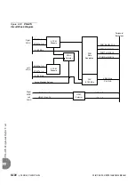
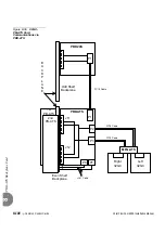
illustrates the PBD-ATS card layout.
The card contains the following elements:
Back view
Two 96-pin connectors, J11 and J12, used to connect the card to the MBP
(backplane) for slot #1.
Two 96-pin connectors, J21 and J22, used to connect the card to the MBP
(backplane) for slot #2.
Front view
Two 34-pin connectors, P2 and P3, used to connect the two FC19 cables that
retrieve the PCM and HDLC signals and the Clock & Synchronization data
from the MPG-ATS card.
See
Even Shelf Cabling: PBD-ATS to MPG-ATS, page 6-29
One 50-pin connector, P1, used to connect the PBD-ATS cards to the PBD24S
of the adjacent odd shelf, (if there is one) via an FC16 (100cm) or FC18
(50cm discontinued) flat cable.
See
PBD24S to PBD-ATS cabling, page 6-33
Two 4-pin connectors, P6 and P7, for the Peripheral Shelf power supply
RPS/PPS Alarm Cabling, page 6-36
P6 is connected to Pin 29 of P3 on the even shelf.
P7 is connected to Pin 27 of P3 on the even odd shelf.
1.
Power must be shut down to the Coral system when replacing any item on the
rear backplane, such as the PBD-ATS.
2.
Remove all cables connected to the PBD-ATS.
3.
Remove screws on the top and bottom of the PBD-ATS.
4.
Grasp the levers and push them outward to eject the card.
5.
Verify that the shrouds between the backplane and the PBD-ATS card are in
place on the backplane.
...................................................................................................
2
Card Description
...................................................................................................
3
Replacing a PBD-ATS Card
Содержание Coral FlexiCom 6000
Страница 2: ......
Страница 4: ......
Страница 18: ......
Страница 28: ...1 10 Introduction Coral FlexiCom 6000 Installation Manual Special Symbols Used in this Document 1 NOTES ...
Страница 32: ......
Страница 51: ...Coral FlexiCom 6000 Installation Manual Hardware Installation Procedure 2 19 Equipment Installation 2 NOTES ...
Страница 80: ...2 48 Hardware Installation Procedure Coral FlexiCom 6000 Installation Manual Equipment Installation 2 4 NOTES ...
Страница 86: ......
Страница 104: ...3 18 Initial Power Up Tests Coral FlexiCom 6000 Installation Manual Common Control Test 3 NOTES ...
Страница 110: ......
Страница 122: ...4 12 Software Installation Procedure Coral FlexiCom 6000 Installation Manual System Database Control 4 NOTES ...
Страница 134: ...4 24 Software Installation Procedure Coral FlexiCom 6000 Installation Manual Upgrading the Coral Version 4 NOTES ...
Страница 143: ...Coral FlexiCom 6000 Installation Manual Chapter 5 External Connections 5 1 External Connections 5 1 ...
Страница 144: ......
Страница 146: ...5 2 External Connections Coral FlexiCom 6000 Installation Manual External Connections 5 NOTES ...
Страница 147: ...Coral FlexiCom 6000 Installation 0DQXDO Chapter 6 Cabinet Descriptions 6 1 Cabinet Descriptions 6 1 ...
Страница 148: ......
Страница 190: ...6 42 Cabinet Descriptions Coral FlexiCom 6000 Installation Manual Cabinet Descriptions 6 NOTES ...
Страница 191: ...Coral FlexiCom 6000 Installation Manual Chapter 7 Power Supplies 7 1 PPS 7 1 7 2 RPS 7 9 7 3 PS ATS 7 19 ...
Страница 192: ......
Страница 210: ...7 18 Power Supplies Coral FlexiCom 6000 Installation Manual RPS Ring Generator Power Supply Unit 7 ...
Страница 224: ......
Страница 322: ...8 98 Common Control Cards Coral FlexiCom 6000 Installation Manual CLA ATS CoraLINK Adapter Card 8 NOTES ...
Страница 338: ...8 114 Common Control Cards Coral FlexiCom 6000 Installation Manual PBD24S Backplane Card 8 NOTES ...
Страница 339: ......


