background image

82

WEB Interface

CP525 cMux User’s Manual Rev. 5.20.12 (3944)

ID: um_tsmux

Configure the mapping that best matches your needs and press apply to activate the new matrix.
Re-configuration does not require re-booting. The choices made will be reflected in the logical
block diagram of the device on the status screen (see also

Section 8.3.1

)

Note:

The port map settings are tagged to follow the device (see

Section

5.7.2

and even though the parameters are exported in the configuration

file format, they are not overwritten when loading a configuration file via

the GUI to another device.

8.4.4 Time Settings

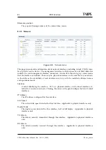
Figure 8.14

Time Settings

The time settings page lets the user configure time zone, the source for synchronising the internal
device time clock and set the internal clock in case of failure of all external sources of clock
synchronisation. The main use of the device time is stamping the entries of the alarm log.

The page consists of four main parts. Top left is the

General

box, containing the following

parameters:

Current time

The current time as reported by the device.

Time zone

Drop-down list to configure the time zone of the unit.

Status

The status of the time synchroniser.

Содержание CP525 cMux

Страница 1: ...CP525 cMux User s Manual Revision 5 20 12 3944 2012 12 17 Valid for SW version 5 20 12 and newer ...

Страница 2: ......

Страница 3: ...ply 21 4 5 1 AC power supply 21 4 5 2 Dual AC power supplies 21 4 5 2 1 AC power cable 21 4 5 2 2 Protective Earth technical Earth 22 4 5 2 3 Connecting to the AC power supply 22 4 5 3 DC power supply 23 4 5 3 1 DC power cable 23 4 5 4 Powering up down 23 5 Functional Description 25 5 1 Introduction 25 5 2 TS inputs 25 5 3 TS output 26 5 4 Input switching 26 5 5 Optional SFN adapter 26 5 6 Video o...

Страница 4: ... window and expired events 43 5 11 3 Notes about the playout sequence 44 5 12 Programming Metadata Communication Protocol PMCP 44 5 13 Scrambling 45 5 13 1 General 45 5 13 2 Simulcrypt setup 45 5 13 2 1 ECMG SCS 46 5 13 2 2 EMMG MUX 46 5 13 3 BISS mode 1 46 5 13 4 Scramble service 46 5 14 Service fallback 47 5 14 1 General 47 5 14 2 Details on confirm timeout handling 49 5 14 3 Manual switching on...

Страница 5: ...face 67 8 1 Login 67 8 2 Status header 68 8 3 Status 69 8 3 1 Current Status 69 8 3 2 Alarm log 72 8 4 Device Info 73 8 4 1 Product info 73 8 4 2 Alarms 76 8 4 2 1 Device alarms 76 8 4 2 2 Global configuration 77 8 4 2 3 Relays and LED 78 8 4 2 4 Alarm log settings 80 8 4 3 Port Mappings 81 8 4 4 Time Settings 82 8 4 5 Network 84 8 4 5 1 Interfaces 85 8 4 5 1 1 Main 85 8 4 5 1 2 Alarms 86 8 4 5 1 ...

Страница 6: ...nces 119 8 5 Scrambling 119 8 5 1 BISS1 120 8 5 2 Conditional Access 120 8 5 2 1 ECM 120 8 5 2 2 EMM 124 8 5 2 3 Alarms 126 8 6 Inputs 126 8 6 1 Inputs Overview 126 8 6 1 1 IP Inputs 128 8 6 1 2 Switch Inputs 129 8 6 1 3 Copy Inputs 130 8 6 2 Input 131 8 6 2 1 Main 132 8 6 2 2 Alarms 134 8 6 2 3 IP 139 8 6 2 3 1 RTP IP Diversity Reception 141 8 6 2 4 Copy 148 8 6 2 5 Services 149 8 6 2 6 PIDs 152 ...

Страница 7: ...201 8 7 2 8 4 EIT sources 202 8 7 2 8 5 Dynamic PSIP 203 8 7 2 8 6 Static SI 205 8 7 2 8 7 PSI SI PSIP editor 206 8 7 2 8 8 PSI SI Editor 207 8 7 2 8 9 PSIP Editor 213 8 7 2 9 Pri Queue 218 8 7 2 9 1 Priority Queues 218 8 7 2 9 2 Default Priority Queues 220 8 7 2 10 Advanced 221 8 7 2 10 1 Automatic PID Remapping 221 8 7 2 10 2 Automatic Service Remapping 223 8 7 2 10 3 Mute 225 8 7 2 10 4 Edit Ex...

Страница 8: ... 10 3 Raw PID multiplexing 249 10 4 Simple local insertion of a progam 250 10 5 Sharing of service component 250 10 6 SFN operation 251 10 7 Seamless SFN 251 10 8 Adding an unsignalled component Ghost PID 252 10 9 Scrambling a service using BISS1 key 253 10 9 1 Verify scrambling setup 254 10 10 Conditional Access 254 10 10 1 Scrambling 254 10 10 1 1 Setting up an ECM connection 255 10 10 1 2 Scram...

Страница 9: ...on 264 A 6 External reference 265 A 6 1 10MHz 1 PPS input 265 A 7 Compliance 265 A 7 1 Safety 265 A 7 2 Electromagnetic compatibility EMC 265 A 7 3 CE marking 266 A 7 4 Interface to public telecommunication system 266 B Forward Error Correction in IP Networks 267 B 1 IP stream distortion 267 B 2 Standardisation 268 B 3 FEC matrix 268 B 4 Transmission aspects 271 B 5 Quality of service and packet l...

Страница 10: ......

Страница 11: ...r adding removing replacing of components 4 6 0 2010 08 13 Port switching feature added Format selection for output ports in Section 8 4 3 in ATSC DVB mode to select between ASI or SMPTE 310M per output copy New 10 port ASI card HW option Number of resyncs on IP input status page Section 8 6 2 3 Override source IP option field on IP TX parameters Added service details and playout content view on o...

Страница 12: ...12 CP525 cMux User s Manual Rev 5 20 12 3944 ID um_tsmux ...

Страница 13: ...provided The manual covers the following topics Getting started Equipment installation Operating instructions WEB interface description Preventive maintenance and fault finding Alarm listing Technical specifications 2 2 Warnings cautions and notes Throughout this manual warnings cautions and notes are highlighted as shown below Warning This is a warning Warnings give information which if strictly ...

Страница 14: ...s should be read before this product is in stalled and operated All operating and usage instructions should be followed The safety and operating instructions should be retained for future reference 2 4 Contact information Our primary goal is to provide first class customer care tailored to your specific business and operational requirements Please contact us at Telephone 47 22 88 97 50 Fax 47 22 8...

Страница 15: ...M and EMM insertion software licence key is required The CP525 supports insertion of unsignaled PIDs on the input Ghost PIDs into outgoing services 3 1 Summary of Features Features of the CP525 include Flexible transport stream processing PID and program filtering Service component filtering by PID value or by component tag Program re multiplexing TS rate adaptation Minimum null packet rate featur...

Страница 16: ... T VIPS Connect SFN adaptation Option MIP insertion 1 PPS timing reference input Seamless SFN compatible Connected to a T VIPS TNS541 TS Seamless Switch two CP525 s may operate in a Seamless SFN network Support for deterministic DVB Megaframe alignment Transmission of transport stream over Gigabit Ethernet Option Forward Error Correction Reception of transport stream over Gigabit Ethernet Option F...

Страница 17: ...figurations Service fallback The feature makes it possible to configure pairs of services where one is back up for the other Switching decision is made based on alarm levels on each service SI download This key is needed to use an external SI system towards the unit Enhanced SI playout This option controls the availability of a few advanced DVB EIT schedule playout parameters Use constant section ...

Страница 18: ...18 CP525 cMux User s Manual Rev 5 20 12 3944 ID um_tsmux ...

Страница 19: ... option Power cord s CD ROM containing documentation and Flash Player installation files Any optional accessories you have ordered Note 48 VDC versions do not ship with a power cord instead a Power D SUB male connector for soldering to the supply leads is supplied 4 2 Installation Environment As with any electronic device the CP525 should be placed where it will not be subjected to extreme tempera...

Страница 20: ...tained in this unit are not fitted with dust insect filters Pay particular attention to this when considering the environment in which it shall be used Make sure that the equipment is adequately ventilated Do not block the ventilation holes on each side of the CP525 4 4 Ventilation Openings in the cabinet are provided for ventilation to protect it from overheating and ensure reliable operation The...

Страница 21: ... power supplies cover the voltage range 100 240 VAC 50 60 Hz During normal operation load sharing is used between the internal supplies In case of a single power supply failure alarms will be raised and the unit will continue operating off the second power supply To guard against failure in the external power circuitry it is imperative to connect each power supply to separate AC mains circuits Ple...

Страница 22: ...n Appendix A prior to con necting the unit to the supply The unit has a Technical Earth terminal located in the rear panel Its use is recommended This is not a protective earth for electrical shock protection the terminal is provided in order to 1 Ensure that all equipment chassis fixed in the rack are at the same technical earth potential To achieve this connect a wire between the Technical Earth...

Страница 23: ...wer connector pin assignment Pin Placement Specification 1 top positive terminal 2 middle negative terminal 3 bottom Chassis Ground To connect the unit to the local DC power supply 1 Use an electronics soldering iron or a hot air workstation to attach the supplied female D SUB power connector to suitable power leads 2 Connect the power leads to your local power supply 3 Connect the DC power connec...

Страница 24: ...24 CP525 cMux User s Manual Rev 5 20 12 3944 ID um_tsmux ...

Страница 25: ...aps SFN Adapter optional 1PPS ASI Input Optional IP TSP Module MUX Service Filter PID Filter PID Remap PSI SI PSIP regeneration PSI SI PSIP modification PSI SI PSIP carousel Management Remote control ETR290 1 Monitoring Alarm generation HTTP XML SNMP Alarm Relay Clock Time base MIP Inserter Rate control ASI output Optional IP Power 230VAC 48DC Figure 5 1 Product block diagram 5 2 TS inputs The CP5...

Страница 26: ...he currently selected source will cause immediate switching to an alternative input in the switching group The signals on each of the inputs in a switching group can be identical or different Fastest switching times are achieved when the signals are identical with respect to PIDs and services The input switching function can be used on both ASI sources and IP sources or any combina tions of these ...

Страница 27: ...ng is according to figure 5 2 The VLAN framing and RTP encapsulation are optional The RTP layer is important for diagnosing network related problems since it contains a sequence number that can be used for packet loss detection The maximum transfer unit MTU for Ethernet is usually 1500 bytes This limits the number of transport stream packets to embed into the outgoing Ethernet IP frames to be betw...

Страница 28: ...n time on the unit due to incompatible configuration settings Configurations can be imported and exported via the GUI It is possible to clone the entire con figuration of one device to another by exporting the configuration of one device and importing it to another Configurations exported via the web GUI are formatted as human readable modifiable XML files These files can be viewed or altered usin...

Страница 29: ...n also be exported using SNMP Details on configuring the virtual alarm relays can be found in the WEB interface section 5 8 Time synchronisation The CP525 contains an internal real time clock that is used for all internal timestamps The internal clock is battery backed up in order to continue operating while the unit has no power The internal time can be synchronised as follows Manual setting From...

Страница 30: ...s shared between several products in the cProcessor product family but not all modules are available on every product 5 9 1 PID Router A PID router module tells the TS Builder which PIDs are present The router is used by the TS Builder to pass on the correct elementary streams from the input to the output New PID values can be assigned to any elementary stream One elementary stream can only be tra...

Страница 31: ...ese are posted to the input PSI SI PSIP database which in turn triggers an event to the TS Builder 5 9 3 PSI SI PSIP playout module The PSI SI PSIP playout module is the reverse of the PSI SI PSIP section filter and generates a continuous streams of TS packets from PSI SI PSIP sections PSI SI PSIP tables that are configured in any Playout mode see section 8 7 2 8 are posted through this module Tab...

Страница 32: ... PSIP playout 5 9 4 Output Priority Queue The right hand part of figure 5 3 represents the TS packet output priority queue of the TSP It indicates that all data is prioritised before being output The CP525 generates a constant configurable output bitrate translating to a fixed number of available packet slots per time unit Data from different sources are mapped to the priority queue on the output ...

Страница 33: ...nput PAT and PMT tables may be transmitted transparently as components through the unit No caching of these tables will be done they are let through on a packet by packet basis 3 Unreferenced PIDs Unreferenced PIDs are components that are not signalled in any services D 1 Table data from internal carousels PSI SI PSIP player When PSI SI PSIP tables are configured for playout via the PSI SI PSIP pl...

Страница 34: ... less than the bandwidth required to play out PSI SI PSIP at configured rate the PSI SI PSIP player will stagger on the queues trying to fill up remaining capacity on the output If the pass through data is not varying too much in bitrate it will actually be able to fill up the stream with the effect of not having any stuffing packets inserted 3 15 1 3 C A 1 2 21 20 19 18 3 B E D1 D2 D3 b R b R b R...

Страница 35: ...ed in the following Section 5 9 5 5 9 5 Output Priority Queue Advanced As mentioned in the previous sub section the CP525 offers a licence protected feature to extend the number of queues for routing of category C data elementary streams from 1 to 15 R b R b R b R b C1 C2 C15 C3 R b C14 R b R b R b R b C1 C2 C15 C3 R b C14 Group 1 Group N Single queues Grouped queues 17 16 3 5 4 N 3 Figure 5 5 Bas...

Страница 36: ... these components will lead to packet drop for the least important PIDs The services coming from other broadcaster will not be affected 5 9 6 Bitrate shaping algorithm R2 Bucket 2 size B2 R1 Total Output Rate Rt Bucket 1 size B1 R2 N 1 Bucket 2 B2 N 1 size 2 R1 n 1 Bucket 1 B1 n 1 size 1 R2N Bucket 2 B2N size 2 R1N Bucket 1 B1N size 1 Arbitration Loop R1 Configured shaping rate B2 configured Max B...

Страница 37: ...om the PID lists to create new PID routing If PSI SI PSIP tables are configured for playout they are generated and posted to the PSI SI PSIP playout module for continuous packetisation and repetition FOR EACH PORT MUX PORTS FIRST Start Re build FOR EACH PRESENT PID IN ORDER LOW TO HIGH Activate Routing FOR EACH PROGRAM IN ORDER OF PAT Map service Map PID Configured Default pass Pass Configured Def...

Страница 38: ...is illustrated in figure 5 8 FOR EACH COMP IN PMT IN ORDER OF PMT THEN NEW CONFIGURED COMPONENTS THEN PCR THEN ECMs Service Mapping Start Map PMT if mode Pass through PID Rule Tag Rule Default Include Global config Map component PID outpid Exclude Stop Sign Stop Uncond No No No Exclude Include Include Global remap PID crash outpid inpid outpid glob remap No TX Yes outpid local remap No Yes No Yes ...

Страница 39: ...erval The repetition interval indicates the maximum time a receiver must wait before the table is received and is therefore an indication of the perceived quality of the service wait time before receiver has fetched all information The dependency between repetition interval and resulting bitrate is dependent on several factors The number of tables that should be played out The size of each table l...

Страница 40: ...lting bandwidth due to repetition rate configuration fits well within the available bandwidth 2 The configured repetition rate results in a bandwidth that is too high compared to the available bandwidth The playout carousel will utilise all available bandwidth 3 Carousel max bitrate is set to a certain value to guarantee a certain amount of Null packets in the outgoing transport stream If the repe...

Страница 41: ...r 3 seconds higher repetition intervals The interval for the first group will increase from 9 to 12 seconds while the interval for the second group will increase from 27 to 30 seconds Note that the scenario above is just intended for illustration In practise the suffered delay will vary dependent on the available bitrate in the stream There will also be a small random variation in the delays due t...

Страница 42: ...red larger than zero In this case the CP525 will actually reduce the transmission interval until the ideal line again is reached This means that the average repetition interval will be fulfilled The back log time is controlled by a configuration parameter Backlog time which is specified as a fraction of the repetition interval The default value is 1 0 which indicates that a table is allowed to be ...

Страница 43: ...ion rate for the most interesting events e g EIT sections CP525 supports a sliding window mechanism to dynamically change repetition rates for different EIT segments during a day A typical goal is to spend more bandwidth on events for the next 24 hours than expired or more future events The process is illustrated in figure 5 12 1 2 3 4 5 6 7 8 9 10 11 12 13 14 15 16 17 18 19 20 21 22 23 24 25 26 2...

Страница 44: ...ut sequence 0 1 2 3 4 5 6 7 2 3 4 5 6 7 0 1 2 3 4 5 6 7 2 3 4 5 6 7 0 1 2 3 4 5 6 7 Playout sequence 0 1 2 3 4 5 6 7 4 5 6 7 0 1 2 3 4 5 6 7 Time Figure 5 13 Event expiration and playout sequence 5 12 Programming Metadata Communication Protocol PMCP Programming Metadata Communication Protocol PMCP specified in ATSC A 76 is a standard for use within digital television broadcast facilities for trans...

Страница 45: ...mbling is a licensed feature and is only available if the licence key is installed Insertion of ECMs and EMMs is licenced by the Conditional Access feature while scrambling with BISS1 is licenced by the BISS key 5 13 2 Simulcrypt setup The scrambling consists of two parts creating connections for exchanging CWs code words for ECMs see section 8 5 2 1 and setting up services for scrambling see sect...

Страница 46: ...g the crypto period is extended using the last control word until a new connection is established This ensures that the signal always will continue encrypted 5 13 2 2 EMMG MUX In this interface the MUX CP525 acts as the server It continuously listens for connections on a predefined port EMM servers are set up as described in section 8 5 2 2 When a client tries to connect the client must be verifie...

Страница 47: ...ts This is also possible without a successful ECM connection as long as a connection is defined Note The setup when using BISS scrambling is identical to Simulcrypt scrambling 5 14 Service fallback 5 14 1 General The CP525 offers a SW module for redundancy on service level The module monitors the alarm level for two services and selects the best service according to the user specified switching cr...

Страница 48: ...as a state machine that uses two timeout values in order to avoid regular switching between the two inputs A simplified state chart of the controller is shown in 5 16 In auto state the switch controller is armed and continuously listens to change in the top level alarm status for each service For each change event the controller evaluates the levels and checks if the switching criteria is met If t...

Страница 49: ...onds may be configured for the major state A special case deserves more explanation multiple alarms with different severity levels during the wait_confirm state The controller is designed so that it will not stay forever in the wait_confirm state and will respond to the most critical alarm The controller has separate timers for each severity level and each timer has an independently configured con...

Страница 50: ...econds the major event alarm timer reaches its confirm_time and the controller will perform a switch The major alarm timer beats the critical event timer in the race to switch Example scenario 3 A major event is detected and the switch controller jumps to the wait_confirm state and the alarm timer for the major event alarm level is started After 10 seconds a critical event is detected and the alar...

Страница 51: ...ervice shows that there is a delay TB between the GPI state change and the actual performance of the switch The first part of the last time line in the diagram shows how the GPI line should be controlled to perform a manual switch if the current level of the GPI is already in the same position as the wanted switch position A pulse of slightly more than one sampling interval is required before pull...

Страница 52: ...ream resulting from combining the two incoming data streams will then be processed as one RTP packet stream RTP IP diversity reception is a licensed feature and is required at the receiver side No licence is required for smallcast transmission Note If the same data streams are received at both sources the sources will act as equal providers of data If received streams at the sources are not identi...

Страница 53: ...nal interface to the CP525 Depending on the module type it may act as a direct bridge to E3 and T3 telecom network lines using coaxial cable or provide a high speed STM 1 OC 3 optical interface employing single or multi mode optical fibre Figure 5 19 A typical SFP module An SFP module may be configurable or non configurable Using a configurable SFP module the parameters relevant to its operation a...

Страница 54: ...25 user interface Device Info Maintenance General by selecting SFP from the Electrical SFP dropdown menu and hitting Apply After rebooting the user interface will reflect the presence of the SFP network interface This is managed the same way as other network interfaces but with an extra WEB page tab to support SFP specific functionality ...

Страница 55: ... IN ACTIVE ASI 1 ASI 2 ASI 3 ASI 4 ASI IN ACTIVE ASI 5 ASI 6 ASI 7 ASI 8 DATA 2 DATA SFP DATA 1 USB Main output port SFP Port USB Port Ethernet Data Ports Alarm Reset Interface 1PPS Input For optional SFN operation Mains Power Connector Technical Earth MUX Inputs or output copies Ethernet Management Port LED replica of front panel Figure 6 1 Rear panel on 2 ASI card variant MUX Inputs GND OPTICAL ...

Страница 56: ...the back panel The back panels of these two variants are shown in figure 6 1 and figure 6 2 Another configuration is with one ASI card that supports 10 ASI connectors as shown in 6 3 The ports have flexible direction control to best meet the usage cenario of the device The CP525 can generate one Transport Stream output and each ASI port can either be used as an output carrying a copy of this TS or...

Страница 57: ...5 X X 6 X X 7 X X 8 X X Table 6 3 Port direction options on 1 ASI card variant ASI port Input Output copy 1 X X 2 X X 3 X X 4 X X 6 1 3 ASI input ports All physical ports configured as inputs are available for use but the number of simultaneously enabled ports is limited by the licence key Number of input ports activated In the four and eight ports configurations each ASI input port has two LEDs a...

Страница 58: ...therwise Upper Not in use for outputs 6 1 5 1 PPS Input The CP525 comes with a 1 PPS input Activating the port is a software option that enables the device to operate as a MIP inserter in SFN networks The 1 PPS port is mounted to the right below the output ports 1 PPS input BNC female 50 ohms 6 1 6 Electrical Ethernet Data Ports The CP525 comes with two Ethernet data ports These data ports can be ...

Страница 59: ...s Green Traffic and link Right Lit Link Blink data tx or rx Green 6 1 10 Technical Earth Connect the Technical earth to a suitable earth point 6 1 11 Alarm Reset The unit is equipped with a 9 pin male DSub connector to provide alarm information Two programmable relays are provided The first relay is always activated on a critical alarm or when the unit is not powered Please refer to section 8 4 2 ...

Страница 60: ...on between pin 9 and 5 or a TTL low on pin 9 will hold the unit in reset if this function has been enabled The connection must be held for 0 5 seconds in order to active the reset This can be used to force a hard reset of the unit from an external control system This pin can also be used as a general purpose input GPI For more details regarding the alarm relay please refer to Appendix on Technical...

Страница 61: ... for the network where the unit will operate Initially therefore the user should change the IP address of the management interface so that access may be gained from the network The CP525 offers two options to alter the user interface IP address through an Ethernet con nection or using a USB terminal interface If your management computer allows setting a fixed IP address change the IP address using...

Страница 62: ... 1 Changing IP address via the Web GUI Changing the default IP address using the Web interface requires that your management com puter may be configured with a static IP address Note Avoid connecting through a network at this stage as this may give unpredictable results due to possible IP address conflicts 1 Connect an Ethernet cable directly between the PC and the Ethernet control port of the CP5...

Страница 63: ...ice Note If several new devices are accessed one after another the ARP cache of the computer from which the devices are being accessed may have to be flushed between each device since the same IP address will be used for different MAC addresses On Windows XP this is done on the command line typing the command arp d 7 3 2 Changing the management port IP address via terminal interface If a static IP...

Страница 64: ...y Example app net ipconfig ip 10 40 80 100 mask 255 255 255 0 gw 10 40 80 1 This will result in the IP address 10 40 80 100 being set The subnet mask is set to 255 255 255 0 and the default gateway to 10 40 80 1 Note The product CD shipped with the CP525 contains a USB driver to use for serial communication with the device on the USB port The MS Windows driver installation script is configured to ...

Страница 65: ...t software detects devices by sending broadcast messages that the CP525 and other T VIPS devices will recognize and reply to with some essential information The PC running T VIPS Detect may be on a totally different subnet than the CP525 such that the device will be discovered regardless of IP addresses and IP submasks Warning Some ethernet equipment might block broadcast traffic Con nect your PC ...

Страница 66: ...66 CP525 cMux User s Manual Rev 5 20 12 3944 ID um_tsmux ...

Страница 67: ...ation 8 1 Login Access the CP525 by entering its IP address in the address field of your favourite browser When accessing the CP525 the first time the progress bar Figure 8 1 should appear while the Flash application is loading from the device Figure 8 1 Flash application loading When the loading of the Flash application is finished the login window see Figure 8 2 is dis played Type the username a...

Страница 68: ...owing the current user name The local device time A button for minimising the header Using this hides a lot of the header information and gives more space for the rest of the page An activity indicator Note The activity indicator shows one box for each request being processed by the unit Each box may change from green to red if ex cessive time elapses during the processing During normal operation ...

Страница 69: ...left of the navigator 8 3 Status The status page presents an overview of the device operational status as well as a log of alarm events There are two sub pages within the status page Current Status Indicates the running status of the device Alarm Log Presents the device alarm log and provides operations for clearing the log or exporting it as a comma separated value file CSV 8 3 1 Current Status F...

Страница 70: ...he unit It is coloured in the same way as the ASI ports and it has a text explaining which IP interface it will transmit data through when enabled To the left of the ASI ports there is one large box per IP interface that can carry data traffic Above the box is the name of the interface Below this is a bar that shows the current IP RX load Below the bar is a box that shows the overall status of the...

Страница 71: ...milar to a LED The colour of the indicator represents the severity level configured for the specified alarm The various severities and colours used are described in Appendix C The Current Alarms table contains six columns Description Description of the alarm condition For sub entries the extended index is shown in brackets To the left is an indicator visual ising the severity of the alarm The indi...

Страница 72: ... provides additional information via a tool tip shown when hovering the cursor over the row The additional parameters are Sequence A number identifying this specific alarm instance This number is incremented each time an alarm condition is raised SubID 1 The primary numerical index of the alarm instance This index is reserved for future use and is always set to 1 in the CP525 SubID 2 The secondary...

Страница 73: ...ooted The log is circular Events occurring after the maximum number of entries has been reached overwrite the oldest entries in the log The maximum number of stored entries is 10000 8 4 Device Info The device info page contains all the information and settings that are not related to a single input or output port It is divided into multiple sub pages accessed via the navigation list to the left In...

Страница 74: ...x Figure 8 7 Device Info navigator Figure 8 8 Product Information the management network parameters are used as device identifiers and remain untouched if the unit configuration is modified It is only intended as a label tag and will not affect the operation of the unit ...

Страница 75: ...minor changes The minor version number is even for official retail releases and odd for beta releases patch_version If minor_version is even patch_version gives the patch level of that version A patch level of zero means the SW is built on the latest code base an even patch_version means this is a released SW patch on a previous release An odd patch_version means that this is a test version If min...

Страница 76: ... Settings 8 4 2 1 Device alarms The page shown in Figure 8 9 provides the administrator with an interface to view the status and configure the behaviour of all alarms related to the system At the top the Reset Alarm Counters button allows resetting all alarm counters simultaneously The page is divided into two parts On the left is a tree that shows all the alarms The colour of the folder icon and ...

Страница 77: ...en clicked clears the alarm counters for the current alarm The right click context menu of the device alarm page provides an option to reset the counters of all the alarms in the Device Info tree 8 4 2 2 Global configuration Figure 8 10 Global alarm configuration This page provides an interface to configure globally the behaviour of all alarms By default ports use the global configuration settings...

Страница 78: ...1 Relays and LED configuration For further details on the physical relays refer to Section A 5 1 The Virtual Relays field shown in Figure 8 11 also includes settings for the so called virtual relays These are programmable status indicators that can be set to react to any specific alarm condition In the simplest case you may want to enable a relay in case a specific alarm ID turns up In another cas...

Страница 79: ...xt Text details PID 113 subid1 Alarm subid1 value Number subid1 1 subid2 Alarm subid2 value Number subid2 2 subid3 Alarm subid3 value Number subid3 1190 port Synonym for subid2 Number port 2 service Synonym for subid3 Number service 102 pid Synonym for subid3 Number pid 2000 In the expressions you may enter parentheses to group sub expressions together Together with the supported list of operators...

Страница 80: ...rm when alarm with ID 200 turns up on port with ID 1 subid2 1 id 200 AND port 1 1 To generate an alarm when alarm with ID 200 turns up on both port 1 AND port 2 id 200 AND port 1 OR port 2 2 Note the last example in the table Here the count threshold value must be set to 2 to get the expected behaviour This is because the expression entered matches two different alarm events port 1 or port 2 and i...

Страница 81: ...ber of physical con nectors installed in the chassis and the meaning of the different choices are Mode Direction of the port with two choices Input Use the port as an ASI input to the multiplexer All input ports can be used but the number of inputs that can be enabled simultaneously is limited by the licence key Number of input ports activated Output Copy Use the port as an ASI output transmitting...

Страница 82: ...t they are not overwritten when loading a configuration file via the GUI to another device 8 4 4 Time Settings Figure 8 14 Time Settings The time settings page lets the user configure time zone the source for synchronising the internal device time clock and set the internal clock in case of failure of all external sources of clock synchronisation The main use of the device time is stamping the ent...

Страница 83: ...y whose status is OK represented by a green indicator Located below the lists is a field to define the maximum allowed time interval between updates from the currently used time source Exeeding this interval the source is considered Not OK and the synchroniser selects the next source in the prioritised list Upon selecting a time source the Timesource Details box at the bottom right of the page pro...

Страница 84: ...ilability of each interface may vary with the installed software licences and operational mode Interface A label identifying the interface If it is a physical interface with virtual interfaces at tached to it an arrow is shown Clicking this arrow will expand collapse the list of virtual interfaces IP Address The IP address configured for this interface Link Speed The current link speed detected fo...

Страница 85: ...e interfaces are not necessarily identical The CP525 has 1 Control Interface and 2 Data Interfaces The second Data Interface Data 2 may be used as either a normal Electrical Ethernet port or as a SFP module port Selection of which to use is found under Maintenance see section 8 4 9 1 8 4 5 1 1 Main Figure 8 16 Main IP settings This page provides the main configuration settings for the physical int...

Страница 86: ...smatch refer to the http en wikipedia org wiki Duplex_mismatch Wikipedia duplex mismatch arti cle http en wikipedia org wiki Duplex_mismatch MAC address The Ethernet Media Access Control MAC address of the management interface Detect configuration Applies to the Control interface only These two boxes enable read and write attributes of the T VIPS Detect IP assignment server module This server is a...

Страница 87: ...u are currently using for management Allow data traffic Tick this box to allow data traffic on this interface It is not possible to enable data traffic on the management interface Multicast router This parameter is not shown in the management interface page The IP address of the multicast router The address here is used in conjunction with the Use multicast router option in the IP Output page Sect...

Страница 88: ...arameters are available for both received and transmitted packets bitrate The total bitrate received transmitted load Interface load measured relative to max speed Total packets The total number of IP packets received transmitted Good packets The number of IP packets received transmitted containing valid CRCs Multicast packets The number of IP multicast packets received transmitted by the interfac...

Страница 89: ...l interface support The page allows adding removing and editing virtual interfaces VLAN using the selected physical interface Editing is done directly in the table Edited fields are shown as yellow Pending deletions are shown in red Once editing is finished clicking the Apply button will commit all the changes Hitting Refresh will cancel all changes Enable Enable disable the virtual interface ID T...

Страница 90: ...rface Control Checked box enables the virtual interface to allow management traffic Ping Checked box enables the virtual interface to respond to ping messages IGMP ver Provides selection of the IGMP version to use Not applicable to the Control interface Below the table are four buttons In addition to the Apply and Refresh buttons there are buttons to enable adding and removing VLANs 8 4 5 1 6 SFP ...

Страница 91: ...configuration has been licensed The settings will not be committed to the module until writing of the file is expressly initiated The SFP Status page shown in figure Figure 8 22 provides an overview of the module status The appearance of the status page and the range of parameters shown depend on the type of module attached Figure 8 22 The SFP status page The Module General Status field displays t...

Страница 92: ... The field heading will reflect whether a STM 1 OC 3 or an E3 T3 module is installed A discussion of the parameters shown is included in the Config pages description The Module type Alarms field is shown if the STM 1 OC 3 module is present and shows all link related alarms settings of the module Red indicates that the alarm has been raised TIM P Trace ID Mismatch Path LOS Loss of Signal AIS_L Alar...

Страница 93: ...ignal RDI Remote Detection Indication WLD WAN Loop Detected EZ Excessive Zeroes PCV P bit Coding Violation OOF Out of Frame LLD Lan Loop Detected LOL LIU Out of Lock CCV C bit Coding Violation AIS Alarm Indication Signal SS System Status Refer to product specific documentation for further discussion of these parameters The Module type Error Counters field displays errors as they occur counted duri...

Страница 94: ...module provides an optical interface for high speed data communications in SDH or SONET networks This page provides access to change the configuration settings of the module As shown in figure Figure 8 23 the page contains four fields to set operational parameters The Alarms and Error counters fields are identical to those described for the SFP Status sub page Editing the configuration settings wi...

Страница 95: ...le Scrambler Tick this box to enable the module internal scrambler Must be ticked to successfully receive scrambled network data Ethernet flow control A tick enables flow control of Ethernet data from the CP525 to the SFP module Flow control prevents data overflow in the SFP module buffer Buffer overflow leads to data loss that would go unnoticed until attempting to decode the data at the receivin...

Страница 96: ...in the SFP Status sub page The E3 T3 Config page The E3T3 module provides an electrical interface for high speed data communications in E3 or T3 networks This page provides access to change the configuration settings of the module As shown in figure Figure 8 24 the page contains four fields to set operational parameters Editing the configuration settings will alter the SFP configuration file store...

Страница 97: ...ce Line length Only applicable for a T3 interface Allows the output signal to be adjusted according to the line length to reach the termination point FEAC Far end alarm and control indication Only applicable for a T3 interface using G 751 line protocol VCAT overhead Only applicable when using the GFP data link protocol VCAT allows arbitrary grouping of VCAT members STS1 or STS3c timeslots to accom...

Страница 98: ...e buffer Buffer overflow leads to data loss that would go unnoticed until attempting to decode the data at the receiving end In the Fault Propagation field check boxes allow to select which TDM network fault s shall cause shut down of the ethernet data flow LOS Loss of signal AIS Alarm indication signal RDI Remote defect indication LOF Loss of frame FEAC Far end alarm and control Whether or not RD...

Страница 99: ...f the configuration page The status of the SFP module is at all times displayed in the SFP Status sub page 8 4 5 2 IP Routing Figure 8 25 IP Routing The IP Routing table lets the user configure IP routing rules for the unit These rules tell the unit which interface to send IP traffic to based on the destination IP address of the traffic Destination The destination IP address to use for matching ag...

Страница 100: ...les may cause loss of contact with the unit Make sure you will still be able to contact the unit with the new settings before applying the changes 8 4 5 3 TXP Settings Figure 8 26 TXP Settings TXP is a T VIPS proprietary HTTP XML based protocol designed to retrieve configuration and status information using WEB HTTP requests TXP exists side by side with an SNMP agent and provides an alternative wa...

Страница 101: ..._text OK data dev time uptimetxt 49 days 21h 56m 09s dev data response 8 4 5 4 SNMP Settings The Simple Network Management Protocol SNMP is used to monitor network attached devices for conditions that warrant administrative attention This page gives access to SNMP settings such as destination IP addresses of trap receivers and community string It Also displays a log of the latest traps sent by the...

Страница 102: ...led The device forwards alarm events as SNMP traps If there are several sub entries an SNMP trap is transmitted for each sub entry The table at the bottom of the page shows the most recent SNMP traps sent by the device For more information about the configuration settings for SNMP please refer to Section 9 4 in Chapter 9 SNMP 8 4 5 5 Tools The ping tool can be used to check for connectivity betwee...

Страница 103: ...mitted with an interval of about 1 second Start Press this button to start the pinging sequence configured above The status of the ping sequence is displayed in the status frame Status values are reset on pressing the start button After pressing the start button the label switches to Stop and the button can be pressed again to cancel the pinging sequence OK responses The number of ping responses r...

Страница 104: ... repetition intervals as configured in GuideBuilder if Auto is selected in the Interval column on the Table Config page Enable Allow GuideBuilder system to connect Port TCP port to accept connections on The port number must be agreed upon with the GuideBuilder system The default port is 1327 Restore mode Decides which tables that should be restored automatically on startup The three choices are No...

Страница 105: ...d upon with the client Server state Status of the embedded download process The table at the bottom shows any active connections The current implementation only allows one connection at a time If the download server is activated and no client connects within the timeout period the device alarm No SI download client will be raised 8 4 7 Clock Regulator This page lets the user configure synchronisat...

Страница 106: ...ference Fine tune External Reference signal is enabled and the internal clock has obtained lock to the reference Current phase offset Phase offset between the internal clock and 1 PPS clock reference given as a multiple of 3 704 ns one period of 270 MHz Current freq offset Frequency offset between the internal clock and 1 PPS clock reference Current drift Compensated frequency offset between exter...

Страница 107: ...hots From here snapshots of the device configuration settings can be taken and stored locally or exported from the device as XML files Also previously stored snapshots may be imported and applied The device allows for up to 8 configuration snapshots to be stored and managed locally not including the current running configuration 8 4 8 1 Save Load Configs Figure 8 33 Saving and loading of configura...

Страница 108: ...e file that would render the device in a non operational state Clicking the button marked Browse prompts the administrator with a standard system File Open dialogue allowing the administrator to select the file of his choice to import Once selected clicking Load Config performs the following actions Transfers the configuration snapshot from the administrator s PC to the device Validates the config...

Страница 109: ...eature sets See Section 8 4 9 1 for a list of features 8 4 8 2 Boot Log This page shows the configuration database status log from the configuration loading at last re boot If the configuration is rejected at boot the previous configuration will not be replaced This page may then be inspected to find the reason for rejection 8 4 8 3 Stored Configs This page provides an interface to management on d...

Страница 110: ...orm actions on the snapshots Activate Loads the selected snapshot as the active configuration of the device The administrator will be prompted to verify the decision as this action will overwrite any unsaved changes on the device Snapshot Stores the current running configuration as a snapshot in the slot selected in the snapshot table This operation will overwrite the snapshot currently stored in ...

Страница 111: ...on Contact T VIPS for further information on the emergency switch unit Communication with the emergency switch is IP based using the UDP protocol Each unit enabled for emergency switch control polls the emergency switch repetitively to determine the switch position The Emergency Switch tab provides the means to configure the behaviour of the CP525 under emergency switch control Figure 8 35 Emergen...

Страница 112: ...36 Edit Rule Opens the configuration pane for the selected switching rule See Figure 8 36 Delete Rule Deletes the selected switching rule Refresh Refreshes the list display Configure Emergency Switch rule Figure 8 36 Configuring the emergency switch The Main settings field has the following parameters Enabled A tick in the box enables this rule Description User defined description of the rule Ip T...

Страница 113: ...tly applied configuration will remain when the connection is broken Block user If this box is ticked no user may change the configuration of this unit if the emergency switch is in the active state At the bottom of the pane the Apply button is used to confirm and apply changes made the Cancel button is used to discard changes and close the pane 8 4 9 Maintenance The Maintenance page centralises in...

Страница 114: ...e and the management interface IP configuration The Product info field provides the following information Product name This is the product model name Software version The version of the firmware image installed in the unit Serial number The manufacturer assigned serial number used for warranty and software licensing Installed boards The name and serial numbers of the circuit boards installed in ea...

Страница 115: ...operational mode Figure 8 38 TS Configuration Mode The choices are DVB DVB transport streams only are accepted ATSC DVB Both ATSC and DVB streams are accepted Caution When switching mode from DVB to ATSC DVB or vice versa the unit configuration is set back to factory defaults and it is then rebooted The Operational Modes frame is visible if the SFP Module SW licence key is installed This provides ...

Страница 116: ...epends on the presence of the Conditional Access SW licence key When changing the operational mode the unit will automatically reboot 8 4 9 2 Software Upgrade Figure 8 41 Software Upgrade The Software Upgrade sub page lets the user upgrade the software of the device The page contains three buttons and a checkbox Browse Prompts the administrator with a standard system Open file dialogue to specify ...

Страница 117: ...ogress is set with the Details field displaying the IP address of the machine from which the loading was initiated The alarm is turned off when the loading is completed or terminated If the Reboot on success option is active the unit will automatically reboot when loading is complete otherwise an alarm New SW pending is set to indicate that a new SW will be used on next manual reboot After uploadi...

Страница 118: ...ence key text file must be copied into the text box not just a portion of the file 8 4 10 Users Figure 8 43 Users page The Users page provides a configuration interface for user management Settings are provided for configuring a password for each privilege level and for configuring automatic login settings You must have administrator previledges to alter the settings Auto login Specifies the user ...

Страница 119: ...hanges to the device configuration When disabled the Web UI will only prompt for confirmation prior to performing severe operations such as device reset Enable GUI scaling If enabled the web interface will be shown with the currently configured GUI scale level It also enables the use of CTRL and CTRL to change scale level When enabling or disabling this option the web interface may hang for some s...

Страница 120: ...mbling This page lets the user configure conditional access parameters that are common to the entire unit The actual scrambling of service components is done one the service config page Section 8 7 2 6 4 Conditional Access supports DVB SimulCrypt version 2 and 3 8 The Conditional Access page has three tabs ECM EMM and Alarms 8 5 2 1 ECM This page allows configuration of ECM scrambling groups To th...

Страница 121: ...of the selected group Remove This removes the selected channel or group It is only enabled if a channel or group is selected To the right of the tree is an area which is empty until a channel or group is selected Selecting a channel lets the user configure this channel See 8 47 The configuration is split into Channel Configuration and Clients Configuration The Channel Configuration contains the fo...

Страница 122: ...nimum duration of a crypto period Lead CW Number of code words sent in advance to build an ECM CW per msg Number of code words needed by the ECMG per control word provision message Max comp time Worst case time needed by ECMG to compute an ECM The Clients Configuration contains a table showing the clients that are configured It is possible to edit the clients directly in the table You can add a cl...

Страница 123: ...ntrol group this ECM will be connected to Access criteria Value defined by CAS for internal usage This parameter is of variable length and must be whole number of characters Use fixed cw Enable the use of fixed Codewords and specify the odd and even codewords used The CP525 will toggle this codewords as normal This mode is primarily for testing and de bugging purposes CP duration The current CP du...

Страница 124: ...nections CA system id Unique value specifying the CAS CA subsystem id CA subsystem id together with CA system id uniquely defines an EMM generator in the whole system Port The port defines on which port the MUX will listen for EMM generator connections Start Stop Clicking this button will enable disable the connection Section TS pkt flag Value specifying the format of the EMMs as MPEG 2 Sections o...

Страница 125: ...sed the given PID value when playing out the received EMMs If this field is disabled the EMMs will be played out with their existing incoming PID value Data id Value allocated by the EMM generator to uniquely identify an EMM private data stream for this CAS Data type Value specifying if the received data is EMMs or private data Bandwidth Current negotiated bandwidth of received EMMs Note Displayed...

Страница 126: ...iew a summary of all the inputs to the device In addition the list also includes the input switchers and their corresponding inputs if configured The labelling of the inputs is a combination of the user defined name of the input and the physical number of the input port 8 6 1 Inputs Overview Figure 8 51 Inputs Overview The Inputs Overview page shows a short table summary of all the inputs of the d...

Страница 127: ... If the port is disabled the indicator is grey Below the table three values as shown They are Total input rate The combined total bitrates of all the transport streams of all the input ports Total effective input rate The combined effective bitrates total minus null packets of all the transport streams of all the input ports Total cache used Number of bytes stored in PSI SI PSIP database for all i...

Страница 128: ...ing the check box and hitting Apply IP Input The name of the IP input consisting of the factory defined label with the physical port number and the user defined name If no user defined label is defined for multicast streams the multicast address is displayed Interface The interface that this IP input is configured to receive data through Last IP Source The IP address that this IP input last receiv...

Страница 129: ...ble four values are shown The first one is the total Ethernet bitrate received The last three are identical to the three values for ASI inputs described in the previous section The Add IP and Remove IP buttons at the bottom of the page lets the user add or remove IP inputs After clicking the Add IP button the Apply button must be clicked before the channel parameters can be edited A new channel is...

Страница 130: ...itch to remove in the datagrid and press the Remove Input Switch button The Reset Stats button is used to clear statistics counters for the switches 8 6 1 3 Copy Inputs Copy Inputs are virtual inputs that may be used to duplicate data from other inputs The copy inputs may eliminate the need for an external Distribution Amplifier The unit treats the Copy Inputs the same way as any other input in th...

Страница 131: ...bout the selected input The choices are Main This page shows a summary of the transport stream currently received on the input in cluding a summary of the running PIDs and services Alarms This page lets the user view the status of all alarms on the input and override the severity of these alarms IP This tab is present only if the input selected in the navigator is an IP input It gives access to th...

Страница 132: ...ght see figure Figure 8 57 Figure 8 57 IP Input Sections In the IP RX configuration section the Enable and Input label fields are identical to those de scribed for the ASI inputs below The rest of the IP configuration and status parameters are described in Section 8 6 2 3 At the bottom of the page the Reset Stats button is located Clicking this will set all satistics counters relating to the selec...

Страница 133: ...ived on the input The value of this parameter depends on the SDT actual being present and decoded on the input Sync detected Shows whether the input transport stream has been synchronised Total Bitrate The total bitrate of the transport stream currently received on the input in Mbit s Effective Bitrate The effective bitrate excluding null packets of the transport stream currently received on the i...

Страница 134: ... service A list of active alarms if any on the service is displayed by holding the mouse pointer over this icon Detailed information about the service is displayed by holding the mouse pointer over the I icon to the right Service Bitrate The current bitrate of the service i e the aggregate bitrate of all the service components Double clicking on a service will navigate to the Services page with th...

Страница 135: ... 59 By clicking on the alarm nodes in the tree the details for the selected alarm is shown in the Alarm details section figure 8 60 The alarm tree has two types of nodes Folder Corresponds to a group of alarms The colour of the folder shows the highest severity of all the alarms belonging to the group The group is expanded or collapsed by clicking on the arrow next to the group The alarm counters ...

Страница 136: ...ee The right hand side of the page shows details about a single selected alarm see figure 8 60 The frame appears when a particular alarm is clicked Its content may vary according to the alarm selected Figure 8 60 Alarm details The alarm details section includes the following information and buttons ...

Страница 137: ... alarm dependent label This field is shown for PID rate alarms The number entered in the box determines the minimum rate allowed for a given PID below which an alarm is raised The default value is shown to the right Alarm turned on Number of times the alarm has triggered If the alarm is filtered this counter will not increase Error count For alarms that are checked continuously this counter shows ...

Страница 138: ...g an item An item already overridden can be edited or removed The Overridden PIDs Services section shows currently overridden sub items The following columns are found in the table Service PID The id of the Sub item New severity The new severity i e the severity after the sub item has been overridden New limit If the alarm has a configurable limit also the limit of the sub item can be overridden a...

Страница 139: ... input The IP RX Parameters field Enable This shows whether the input is currently enabled The input is enabled or disabled by clicking the check box and then apply Receive port The UDP port on which this input will listen for data Presumed jitter The maximum amount of jitter you expect on the ip link This value controls the amount of buffering that will be applied Join multicast If this box is ch...

Страница 140: ... IP stream received by this input If the input has never received an IP stream this value is set to 0 0 0 0 Total rate The total IP rate received on this input Latency This parameter reflects the network jitter the unit can handle at the moment Min Max latency This shows the minimum and maximum latency measured since the statistics was last reset Protocol Indicates RTP if the received data contain...

Страница 141: ...ption This tab will only be visible if a diversity input has been added Please see 5 15 for detailed technical description of RTP IP Diversity Reception The Diversity sub page is shown in figure 8 63 This page allows configuration of the IP parameters for the two IP inputs that form the diver sity reception Additionally detailed IP status information for both channels and the diversity reception i...

Страница 142: ...ows whether the input is currently enabled The input is enabled or disabled by clicking the check box and then apply UDP received port The UDP port on which this input will listen for data Join Multicast If this box is checked the input will join the multicast configured in the following IP field If the box is not checked the input will listen for unicast traffic if this parameter is box is checke...

Страница 143: ...lowing IP field If the box is not checked the input will listen for unicast traffic if this parameter is box is checked it is possible to enter the multicast group address the input will join Source interface The interface on which this input will listen for data IP Source B Status Last IP source The source IP address of the last IP stream received by this input If the input has never received an ...

Страница 144: ...sport with equal transport delay within 1ms By pressing the button Remove diversity input IP source B will be removed and source A will resume to be a standard IP source again The Manual re sync button will resynchronize the data storage buffer being used by both IP source A and B The FEC sub page is shown in Figure 8 64 This page displays the status of the forward error correction processing of t...

Страница 145: ...f rows used in the FEC matrix of the incoming signal Max IP frames delay The maximum delay of out of order IP frames datagrams Latency required The latency required by the input FEC processor to handle the incoming FEC matrix The Column Stream Status and Row Stream Status fields show the status of the IP stream carrying the column and row FEC IP datagrams respectively UDP port The UDP ports receiv...

Страница 146: ... encounter before it is discarded OK responses Indicates how many valid Ping responses have been received Timeouts Indicates how many of the sent Ping messages timed out i e did not provide a valid response within the allowed time Last roundtrip The time taken from last sending the Ping message until the response is received Min roundtrip The minimum time taken from sending a Ping message until th...

Страница 147: ... sufficient to handle signals from professional DVB equipment at the same time guaranteeing that the output bitrate does not deviate beyond 25ppm If you want to synchronise to streams coming from sources with less accurate clocks you may have to configure a wider operation range to allow the output clock to be tuned further off to avoid buffer over underflow Max bitrate If VBR rate mode is chosen ...

Страница 148: ...e output bitrate with respect to the initially measured input bit rate in order to avoid buffer under overflow Regulator operation range Indicates the maximum clock correction in ppm that may be applied This parameter is affected by the Expected PCR accuracy parameter and is typically configured slightly wider to allow headroom for buffer regulation Channel uptime The elapsed time since last re sy...

Страница 149: ...opy Input 8 6 2 5 Services The Services page displays a list of services running in the selected input Each service type is represented by a symbol coloured to show the current alarm status of the service figure 8 68 Figure 8 68 Service details overview when service list is not expanded ...

Страница 150: ... the PIDs pertaining to the service PMT PCR ECMs and the component PIDs signalled in PMT If PIDs are shared between services the displayed sum of the bitrates of all services may exceed the total bitrate of the transport stream Min rate The minimum bit rate measured for this service since the last reset Resets when the PID rates are reset Max rate The maximum bit rate measured for this service sin...

Страница 151: ...a table showing all alarms currently active on the selected service The columns in the table Severity Description Alarm ID and Details have the same meaning as described in Section 8 3 2 The Service Descriptors sub page is divided into two sections The first section Service Descrip tors shows a tree with all service descriptors if present The second section SDT Descriptors shows a tree containing ...

Страница 152: ...that in grid view a list of descriptors may be displayed below the Components table when clicking on a component A tree structure of descriptors is displayed if present in the selected component 8 6 2 6 PIDs This page gives detailed information about the PIDs present on the input Two different PID views may be selected with buttons on the tool bar at the top of the page The Grid button selects a l...

Страница 153: ...a PCR PID 3 This icon is shown if the PID is scrambled and the scrambling bit is odd 4 This icon is shown if the PID is scrambled and the scrambling bit is even 5 This icon is shown if the PIDs priority bit is set PID This is the packet stream id Type This is the packet stream type Unsignalled PIDs have no type Bitrate This is the current bitrate of the packet stream in Mbit s Min Rate This is the...

Страница 154: ...streams containing descrambling information for this PID Count Number of packets counted for this packet stream since last couter reset Beneath the PID table are three buttons Reset CC error counts This resets the CC error counters for all packet streams Reset min max rates This button resets the min and max bit rate measurements for all packet streams Reset packet counts This button resets the pa...

Страница 155: ...nput SI PSIP database of the device Accessing the related sub pages gives access to table contents right down to byte level Which tables being currently analysed by the device is also displayed Tables tab The button switches to a detailed view of the tables present on the input and analysed by the device Settings tab This button switches to a page showing what tables are being analysed Sources tab...

Страница 156: ...ip describing the meaning of the secondary ID in the context of this table Tertiary The tertiary extension ID of the table Hovering the mouse cursor over the value displays a tool tip describing the meaning of the key in the context of this table Ver This is the last received version of this table Age The time elapsed since the table was last updated Selecting a single table from the tree to the l...

Страница 157: ... been changed by another user Figure 8 74 shows the page as displayed in DVB mode In ATSC mode the page looks different as shown in figure 8 75 Note Turning off analysis of certain tables may impact the output stream Please make sure none of the tables you turn off analysis for are used by the output See below for examples Examples To be able to see the programs and do service filtering on an inpu...

Страница 158: ...licking each timeout parameter and selecting Set to default resets the original value The timeout values are also used to generate Table missing alarms The Sources sub page is shown in figure 8 74 This page allows you to configure non standard input PID values for the section filtering of individual SI PSIP tables This makes it possible to filter out SDT other on a PID of choice while SDT actual i...

Страница 159: ...ub pages for a switch a list of current alarms is shown This list is identical to the list displayed in the Current Status view and described in section Section 8 3 1 8 6 3 1 Main The Main sub page is used to configure input switching of a group of inputs The page is accessed by selecting a switch in the left hand side navigator on the Inputs tab or by double clicking the switch entry on the Input...

Страница 160: ...id input are in sync and does not have a Critical alarm condition If disabled switching is only done manually by selecting port and pressing Switch To If disabled the alarm Auto switching disabled will be set to warn that no auto switching will happen If disabled the unit will remember the selected input even during power loss Switch wait Time to wait before switching in case switching condition d...

Страница 161: ...her prioritized sources Add port by selecting the port in the drop down list and pressing Add Remove a port by selecting the port in the grid and pressing Remove Switch manually to a port by selecting it in the grid and pressing Switch To Note When doing manual switches in Automatic switch mode the switch might automatically switch away from the selected input after the Return Wait time has passed...

Страница 162: ...ently transmitted in Mbit s Alarm Status The current alarm status of the output is shown as a coloured circle 8 7 2 Output Figure 8 79 Output header When selecting an output a new page on the right hand side with information about the selected output is displayed The top part of that page is common for all sub pages and is divided into two main sections The left hand section shows the name and the...

Страница 163: ...input PIDs prior to building the output transport stream Tables This page is used to configure the behaviour of the PSI SI PSIP signalling Pri Queues This page is used to manage the output priority queues for traffic prioritisation and shap ing Advanced This page contains sub pages with various settings Outgoing This page shows a detailed view of the PIDs and services in the output transport strea...

Страница 164: ...ate This shows the current measured total bitrate of the output transport stream This value may vary slightly from the configured value due to measurement errors Effective bitrate This shows the effective bitrate of the output transport stream Forced stuffing This parameter is used if there is a need to guarantee a minimum amount of null packets PID 8191 in the output transport stream When enabled...

Страница 165: ...nables you to select how to handle TS ID and Original Network ID in regenerated PSI SI tables Remap TS Identifiers Check this box to manually enter the TS ID and Original Network ID to use for the output stream In ATSC mode Original Network ID can not be overridden If the box is unchecked you must select the input that carries the TS ID and original network ID that should be auto tracked The OFDM ...

Страница 166: ...he first page of the configuration wizard you choose the main mode of operation This will decide what pages are shown later in the wizard The modes are Priority per service In this mode the wizard will create a set of priority queues for each service type Television services will be given the highest priority then Radio services and then all the others Within a service the components will be assig...

Страница 167: ...he right arrow button to move them to the right list All service in the list to the right will be configured to be transmitted when finish is clicked at the end of the wizard Step 3 Priority Queue setup Figure 8 84 Configuration Wizard Step 3 Depending on the choices made in the first two steps the wizard creates a number of priority queues In this step the user can modify the shaping bitrate and ...

Страница 168: ...he services to a different service ID on this page Figure 8 86 Configuration Wizard Step 4 Priority per component type If the chosen mode of operation is priority per component type this step shows a list of all component types detected in the chosen services For each component type it is possible to assign one of the pre configured priority queues 8 7 2 2 Alarms The Alarms page lets the user conf...

Страница 169: ... confirm Interface The port of the output Resolved Indicates Yes if the IP destination has been reached Destination IP address and port number of the destination FEC Settings Shows if output FEC has been applied and the column and row sizes as applicable Bitrate The total output bitrate including FEC if applied Double clicking on a table line takes you directly to the specific page for configuring...

Страница 170: ...this sets the corresponding bit in the MIP packets TPS TS priority Whether to signal HP high priority or LP low priority in the 5 tps_mip TS priority field Enable check box to signal HP This is not the same as the TS priority bit field in the TS packet header which is always set to 1 The second section contains status parameters about the transmitted MIP packets OFM mode Status showing whether out...

Страница 171: ...itters you haven t added a specific configuration for By entering a specific transmitter ID the configuration shall only be used by the transmitter with that id Transmitter time offset Function tag 0x00 defined in 5 Transmitter frequency offset Function tag 0x01 defined in 5 Transmitter power Function tag 0x02 defined in 5 Private data Function tag 0x03 defined in 5 Value is typed in as a hex stri...

Страница 172: ...ator 1PPS or GPS and external TimeSource SNTP or GPS Initial offset Initial measured offset between external TimeSource and Clock Regulator This is the offset found when doing a SFN resynchronisation Current offset Current measured offset between external TimeSource and Clock Regulator The difference between the Initial and Current offsets will give the current drift between the external TimeSourc...

Страница 173: ...packet Clicking the refresh button will fetch the current packet being sent 8 7 2 5 Services The Services page Figure 8 91 lets the user configure which services to transmit and which to stop selected from the services available in the input The user can also remap service ids from this page and perform service component manipulations At the top of the page the user may choose to pass one or more ...

Страница 174: ...always appear in the transmitted table and a service configured to Stop will always appear in the stopped table Present This tells whether the service is currently present in the input signal Therefore it also tells if a service configured to be transmitted is actually transmitted If the present column says no it is not present and therefore not transmitted Services that are not present in the inp...

Страница 175: ...n is always active When clicking it a new dialogue opens where the user can select what input the configuration should apply to what service ID of the chosen input the configuration should apply to what ID the service should have in the output and what kind of configuration to apply This can be used to apply a configuration to a service that is not currently present on the input Edit This button a...

Страница 176: ...selected service s will be stopped The change is immediate with no extra request for confirmation Clear Config This button becomes active when selecting one or more services with a configuration applied to it It removes the configuration from the selected service s This means that the services will be handled according to the default service behaviour 8 7 2 6 Service edit dialogue As seen above th...

Страница 177: ...will replace the service ID found in the input PAT and PMT Allow Auto SID If enabled the Output service ID may be remapped automatically using the Automatic Service ID remapping feature described in Section 8 7 2 10 2 If disabled the configured Output Service ID will be used PMT Playout remap Check this box if the output PMT shall have a different value from that of the input PMT Enter the new PID...

Страница 178: ...pped It is also possible to remap PCR PIDs by adding a reference to the PID in the component list of the Components tab Thus if a service has PCR embedded in one of the component PIDs it is preferable to configure re mapping using the Component tab Config Mode Whether to write a Stop or Transmit config entry for the service The other parameters are only relevant if this parameter is set to Transmi...

Страница 179: ... Overriding of SDT fields requires that SDTa analysis is turned on on the input that there is an SDT on the input and that SDTa is set to Playout Regenerated on the output The fields that can be overridden are Service name Name from service descriptor Service provider Provider name from service descriptor Service type Type from service descriptor Running status Running status field from SDT servic...

Страница 180: ...hannel transport stream ID in the VCT Program number Overrides the program number in the VCT This should normally be left unchecked to follow the remapping of the program number Source ID Overrides the Source ID field in the VCT Remark that the value chosen here must link to a source ID in the EIT on the output Modulation mode Overrides the modulation mode in the VCT Service type Overrides the ser...

Страница 181: ...to add replace or remove descriptors in PMT or SDT respectively This is done by pressing Add Rule which brings up the dialogue as shown in Figure 8 96 Note that this dialogue is slightly different when removing a descriptor which only requires that the tag value is entered Descriptor tag Specify the descriptor tag value in hexadecimal notation for the descriptor you want to ...

Страница 182: ...l state if the length of the descriptor payload is outside spesifications 8 7 2 6 3 Service Edit Components Figure 8 97 Service edit dialogue Components tab In the Components page the user may perform filtering and remapping of service component PIDs Components rules may be added either by matching PID value or by matching component tag from the stream identifier descriptor if this is present on t...

Страница 183: ...T of the service and the results of configuration rules that have been added to the service The components displayed include the ECM PIDs found in CA descriptors associated with the service PID rules may be added to match a shared separate PCR PID as well even though such PCR PIDs are not displayed as a component in the grid When clicking a row a request is launced towards the unit to collect the ...

Страница 184: ...ation Figure 8 98 points at important screen elements on the Components tab There are three main operations in the component dialogue Add Remove and Edit These are described in the following The Add button This is used to add a new service component that is signalled in a service on any input port s or to add a custom component In this way you may add configuration for a service component that is ...

Страница 185: ...map to PID 1200 PID shared by two or more services on the input Exclude config added for PID not currently in incoming PMT Signalled in incoming PMT but not present will be stopped Present Excluded by default rule Present Included Component has a Tag rule Component has a PID rule Figure 8 98 Component dialogue Important elements Figure 8 99 Component add dialogue Components tab Single Multiple ...

Страница 186: ...ng parameters for the component can also be set here They are described in the edit component scrambling chapter Section 8 7 2 6 4 Clicking the Add button and selecting Custom brings up the dialogue as shown in figure 8 100 This dialogue shows the status of the added component The drop down menu lists all the custom components added in this CP525 When a component is selected from the list the stat...

Страница 187: ...g Add Descriptor See section 8 7 2 6 2 for further information The Remove button This button removes entries that have previously been added This only works for entries labelled with a plus sign The Edit button The handling of a present component can be determined by selecting the row or multiple rows and clicking the Edit button below the grid in Figure 8 97 This pops up another dialogue 8 102 wh...

Страница 188: ... input PID The field is mainly intended for use in time share multiplexes where a PID moves between services at different times of the day and a different output PID is required in each service Also this field may be used on a tag rule to achieve a fixed output PID for a given tag in this service even when the input PID changes If a configuration renders a PID conflict an alarm will be raised by t...

Страница 189: ... is a licensed feature and this tab is only visible if the licence key is installed Scrambling mode This Drop down can be set to one of two values Only signal In this mode no actual scrambling of components will be done but the components will be signalled as scrambled according to the scrambling configuration Scramble In this mode the components will be scrambled according to the scrambling confi...

Страница 190: ...bling parameters as described in Section 8 7 2 6 4 Edit Figure 8 104 Scrambling edit dialogue Scrambling tab The scrambling of a component can be edited by selecting the row or multiple rows and clicking the Edit button below the grid This pops up another dialogue 8 104 where rules for this component may be added or edited The same can be achieved by double clicking the row or right clicking and s...

Страница 191: ...ponent will be signalled according to the service default Don t signal Scrambling will NOT be signalled as a CA descriptor on the component level of the PMT Signal Scrambling will be signalled as a descriptor on the component level of the PMT The Tag Config frame is used to add a rule that matches the tag Normally one would choose either to use a PID rule or a Tag rule for one component If both ru...

Страница 192: ...on shows the current status of the switch It shows the main and spare ports and which of them is active at the moment The state of the switch is also shown The switcher has the following states Active While in active state the alarm status of the active input is monitored If it changes to a severity that has switching enabled the alarm severity of the spare input is checked If it is lower than the...

Страница 193: ...her with parameters to enable switching based on GPI Read more about switching based on GPI in Section 5 14 3 GPI input state Shows whether the GPI input state is Active or Inactive Enable GPI switching Choose whether switch controller should react to GPI state changes GPI polarity Option to invert the logic on which service is selected when GPI goes active Normal means spare is selected if GPI tu...

Страница 194: ...her rules are applied to the PID Press the Apply button next to the Drop down menu to activate the setting Any new unsignalled PID appearing on the input will then be passed on Beneath the Drop down menu are two tables The left hand table shows all PIDs that have no configuration added the right hand table shows all configured PIDs When a configuration is added to a PID it will disappear from the ...

Страница 195: ...ration will only apply to the selected PID if it comes from the specified source input In PID This is the input packet id The blue information icon carries more information about the PID in its tool tip Out PID This is the packet id allocated to the transmitted packet Remapping a packet id will cause this id to be different from In PID New Edit Add Remove Figure 8 107 PID configuration buttons Bet...

Страница 196: ... input Src Input The input port the PID is coming from Type The PID type empty for unsignalled PIDs Priority The priority to use for this PID routing This field determines in which priority queue the TS packets for this PID are put when routed through the unit The priority level determines which data to drop first in the event of an overflow See separate chapter for a description of the different ...

Страница 197: ...2 8 Tables The Tables page allows the user to configure the playout of PSI SI tables It is divided into several sub pages Toggling between pages is done by clicking on the icons at the top of the Tables page 8 7 2 8 1 Main In this page the user can configure the backlog time for table playout EIT packing and the way to play out supported tables Note that Backlog time and EIT packing are not visibl...

Страница 198: ... that start with the word Passthrough implies that the table is passed through the unit by mapping a PID stream through much the same was as for the video and audio elementary streams When a table is treated in Passthrough mode all other table types that are transmitted on the same PID must be treated the same way In these modes it is not possible to configure a new repetition interval for the tab...

Страница 199: ...of BAT and SI other tables SDTo NITo EITpfo EITso while the SI actual tables are set to Playout Regenerated For PSIP tables other than TVCT CVCT this is the only supported playout mode Note that it is also possible to configure pass through for the tables in the PSIP base PID 8187 Playout Downloaded This mode is used in conjunction with the SI PSIP Download server described in Section 8 4 6 The ta...

Страница 200: ...what is wrong You will not be able to apply the changes until the errors have been cleared Note If you are remapping TS ID and Network ID or changing the service composition of the output you would normally configure PAT CAT PMT and SDT actual to Playout Regenerated In addition EIT p f actual and EIT schedule actual can be configured to Playout Regenerated to ensure that only the sub tables for th...

Страница 201: ...egment Use constant section interval This parameter is only effective when the arbitration mode is set to Section The parameter specifies how the sections of a particular table indicated by a table ID will be played out If set to true the player will calculate an average section repetition interval for all groups and play out exactly one section at the end of each interval If set to false each gro...

Страница 202: ...e PID of ETT 0 Number of EITs ETTs Number of EIT and ETT tables being sent minimum 4 and maximum 128 Interval ms The repetition interval for EIT 0 and ETT 0 as configured on the main Table Configuration page Increment ms The increment in repetition interval between table EIT 0 and EIT 1 and between EIT k and EIT k 1 Note The playout of EIT ETT requires that analysis of input EIT ETT tables is enab...

Страница 203: ...egenerated mode 8 7 2 8 5 Dynamic PSIP This page is only available when the output has been set to ATSC mode On this page it is possible to configure the reception of PMCP EPG data The data received will be processed and can be played out as PSIP tables from an event database For technical details see section 5 12 The configuration interface can be seen in figure 8 113 The interface is split in tw...

Страница 204: ...this would correspond to http server_address pmcp PMCP XML file prefix To recognize the files in the given path all files must start with a given prefix The default value is PMCP_ which dictates that all XML based PMCP files must start the file name with PMCP_ I e on a HTTP server this would correspond to a file name similar to http server_address pmcp PMCP_filename xml Max Number of local files T...

Страница 205: ... Static SI configuration The static PSI SI tables used for playout is added trough this page figure 8 115 Tables are added by using the Add button or removed using the Remove button When adding a table a dialogue is displayed where you can paste the table sections as an ASCII encoded hexadecimal string Figure 8 116 Only one table can be committed at a time When adding tables with more then one sec...

Страница 206: ...ted table under Tables on a T VIPS CP545 or equivalent equipment 8 7 2 8 7 PSI SI PSIP editor Figure 8 117 PSI SI editor tree The PSI SI PSIP editor allows the user to edit PSI SI PSIP tables manually The user can build the tables from scratch or import tables from an input port a file the currently transmitted data or the currently stored static tables After editing the tables the user can genera...

Страница 207: ... a file Generate This generates the table sections for the selected transport stream If no transport stream is selected when pressing Generate a dialog will be shown where the user can choose the transport stream to generate tables for The transport stream configuration defines what table types to generate The default is that all tables are generated The Compiled Tables dialog is then opened On th...

Страница 208: ... as shown in Figure 8 118 Here the user can change the network ID The user can also remove the network add a transport stream to the network or add a NIT descriptor to the network The mandatory network_name_descriptor is added automatically and allows the user to set the name of the network Transport Streams Figure 8 119 Transport Stream Each network can have any number of transport streams belong...

Страница 209: ...bles to generate When generating table sections for this transport stream the selected table types will be generated By default all the tables are selected Remove transport stream Clicking this button will remove this transport stream from the network Add channel By clicking this button a new channel will be added to this transport stream and then it will be selected in the tree Add NIT descriptor...

Страница 210: ... shall take the value of 8191 This default value of this field is 8191 Running status This sets the current status of the service EIT schedule flag If selected this field indicates that EIT schedule information for the channel is present in the current Transport stream EIT p f flag If selected this field indicates that EIT present following information for the service is present in the current TS ...

Страница 211: ...ing the icon to the right the user can select from a list of possible stream types Elementary PID This field specifies the PID of the Transport Stream packets which carry this program element Remove component Clicking this button will remove this component from the channel Add PMT descriptor Opens the Add Descriptor dialog to add an PMT descriptor to this component Bouquets Figure 8 122 Bouquet By...

Страница 212: ...f available services Remove service Removes selected channels from the bouquet Add BAT descriptor Opens the Add Descriptor dialog to add an BAT descriptor to this bouquet The bou quet_name_descriptor is added automatically when the bouquet is created Add Descriptor Dialog Figure 8 123 Add Descriptor Dialog By choosing to add any type of descriptor the Add Descriptor Dialog is shown Figure 8 123 Th...

Страница 213: ... as a hex string The entered data is continuously decoded in the Payloaded Decoded box Payload decoded This box shows the decoded descriptor using the currently entered payload It will show an error if the payload is not legal Descriptor syntax This box shows an xml describing the syntax of the descriptor The structure of this xml is beyond the scope of this manual Remove descriptor Clicking this ...

Страница 214: ...s Transport Stream from any other multiplex The default value is 0 Tables to generate When generating table sections for this transport stream the selected table types will be generated By default all the tables are selected Add channel By clicking this button a new channel will be added to this transport stream and then it will be selected in the tree Add CAT descriptor Opens the Add Descriptor d...

Страница 215: ...S time 00 00 6th of January 1980 If the user does not tick the box the unit will set the offset to the correct value based on the leap seconds added when the unit software was built This field should only be overidden if there has been leap seconds since the software was built In daylight savings time If this box is ticked it indicates that daylight savings time is currently in effect Transition w...

Страница 216: ...ision or ATSC audio only shall use minor numbers between 1 and 99 For other types of services such as data broadcasting valid minor channel numbers are between 1 and 999 Short name The name of the virtual channel max seven characters Channel transport ID A field that represents the MPEG 2 Transport Stream ID associated with the Transport Stream carrying the MPEG 2 program referenced by this channe...

Страница 217: ...d when the user is channel surfing and appear as if undefined if accessed by direct channel entry Typical applications for hidden channels are test signals and NVOD services Whether a hidden channel and its events may appear in EPG displays depends on the hide guide field Hide guide Indicates if not selected for a hidden channel that the channel and its events may appear in EPG displays This field...

Страница 218: ...e configuration affects the sequence in which packets are transmitted on the output and which packets that are dropped first in case of an output overflow Figure 8 128 Basic output priority queue default config The priority queue is presented in a data grid with the highest prioritised queue at the top lowest priority at the bottom Figure 8 128 shows this view for the basic priority queue variant ...

Страница 219: ...atistics The number to the right of the diagram shows the max number of packets that can be buffered in this queue This column also shows status info for the forced stuffing packet source Pkt Cnt Number packets transmitted on this queue Lost Number of overflows detected on a queue This number is not the same as the number of TS packets lost on the queue Min max rates and packet counters are cleare...

Страница 220: ...pping packets and an overflow alarm will be set with the sub id indicating the queue number and the details field listing the queue name 8 7 2 9 2 Default Priority Queues This page is used to set default queue priorities per input port The default priority is used when no priority is defined or when explicitly using the ports default priority in Service or PID configurations When using the default...

Страница 221: ...purposes and is not commonly used in normal multiplexing operations Several of the advanced features found on this page requires a licence key to be visible and properly functioning 8 7 2 10 1 Automatic PID Remapping The configuration of automatic PID remapping can be seen in figure 8 131 Figure 8 131 Configuration of automatic PID remapping The formula for remapping of PID values are described be...

Страница 222: ...ond video pid 512 1 x 4 1 x 2 0 x 1 518 Service 2 The resulting PID remapping from ASI4 would be First video pid 512 3 x 4 0 x 2 0 x 1 524 Service 1 Second video pid 512 3 x 4 1 x 2 0 x 1 526 Service 2 The end result will be four video PIDs transmitted by the multiplexer at the following values Video PID 516 ASI2 Service 1 Video PID 518 ASI2 Service 2 Video PID 524 ASI4 Service 1 Video PID 526 ASI...

Страница 223: ...ther Start and End PID forms the PID range for the specified rule type In the case where the start value is higher than the end value the remapping will be reversed top to bottom End PID Defines the PID end value for the specified rule type Make sure to assign a big enough range for all the PIDs that you want to remap Port offset This parameter defines the amount the PID values will be stepped up ...

Страница 224: ... further be mapped to service ID 17 since service ID 16 is occupied by Service 1 The end result will be four TV services transmitted by the multiplexer at the following IDs Service 6 ASI2 Service 1 Service 7 ASI2 Service 2 Service 16 ASI4 Service 1 Service 17 ASI4 Service 2 In the case where the amount of remapped service IDs exceed the configured range defined by the rule types the multiplexer wi...

Страница 225: ...start value for the specified rule type Together Start and End ID forms the service ID range for the specified rule type In the case where the start value is higher than the end value the remapping will be reversed top to bottom End ID Defines the service ID end value for the specified rule type Make sure to assign a big enough range for all the service IDs that you want to remap Port offset This ...

Страница 226: ...matic actions will be taken by the controller Return mode If set to Return if OK output muting will be reverted when none of the criteria are active and the hold period has passed If set to No return manual interaction will be needed to take the controller out of a mute To the right there are two buttons used for manual operation of the mute controller Manual operation is always possible either to...

Страница 227: ...of the criterion list there are three status fields Number of timers This shows the number of integration timers that are currently running Timer This field shows the criterion integration timer that is closest to expiry i e the time to a muting action can be expected if currently unmuted Active criteria Current number of active criteria Note When choosing a value for a criterion integration timer...

Страница 228: ...relay Ports List of available ports For port alarms it is possible to filter on given ports Expression Expression resulting from selections made in Alarms list and Port list or manually typed expression 8 7 2 11 Outgoing The Outgoing page shows PIDs and services that are currently being transmitted on the output It has four sub pages Services Service Routing PIDs Tables 8 7 2 11 1 Services This pa...

Страница 229: ...gure 8 136 Outgoing Services Routing The page has a table showing the services that are currently being transmitted on the output with reference to the input port of the service The table has the following columns Input port The input port of the service Input Service ID The Service ID program number of the service on the input port Input Service Name The name of the service as described in the Se...

Страница 230: ...transmitted on the output The table has the following columns Info This column shows the same icons as in figure 8 71 explained in Section 8 6 2 6 except that the PCR detection is not available on the output PID The Packet Id Type The PID type Unsignalled PIDs do not have a type Bitrate The current bitrate of the PID in Mbit s Min Rate Max rate The minimum and maximum recorded rates of the PID sin...

Страница 231: ...es a count of the number of TS packets sent for this PID Input Port Reference to the input port this PID is routed from If internally generated thus played out by the PSI SI PSIP player the column shows a dash Input PID The original PID value on the input port Beneath the table are three buttons The Reset CC error counts button resets the CC error counters of all PIDs The Reset min max rates butto...

Страница 232: ...put Click the Change to ASI input button and confirm with Apply Clicking on one of the IP interface entries opens the page that allows setting all relevant para meters for that IP output 8 7 4 TS OUT IP Destination This page allows configuration of the IP output port This page consists of the sub tabs Main and Ping If Forward Error Correction has been enabled the FEC tab is also visible 8 7 4 1 Ma...

Страница 233: ...e same UDP source port as the media frames Type of service TOS Enter Type of Service parameter as a byte value to be set in the Type of Service TOS field in the IP header as specified in RFC 791 This parameter is used for Class of Service prioritisation Its usefulness depends on routers honouring this field Please refer to Appendix E Quality of service Setting Packet priority for further details T...

Страница 234: ...he interface depends on the configured destination address and the configured IP routing entries Resolved Yes when the MAC address of the configured IP destination address is resolved The parameter is always Yes when multicast is used without a multicast router No when the MAC address is not yet resolved by ARP lookup Dest MAC address Shows the destination MAC address used for the stream This may ...

Страница 235: ...rhead resulting from the applied FEC Resulting total rate Shows the actual bit rate of the IP stream including FEC if applied The Common FEC Configuration field allows setting of common parameters that will be applied to the FEC processor in general Number of columns L The number of columns used in generating the Row FEC data Number of rows D The number of rows used in generating the Column FEC da...

Страница 236: ...nent on the way to the receiver Ping helps resolving such issues by sending a short message regularly This feature also makes it possible for the receiver to monitor if an active sender is present The Settings field Enable Unicast Peer Ping Check this box to enable Unicast Peer Ping This enables regular pinging of the receiving device Interval Set the interval in seconds between each Ping The Stat...

Страница 237: ... the allowed time Last roundtrip The time taken from last sending the Ping message until the response is received Min roundtrip The minimum time taken from sending a Ping message until the response is received Max roundtrip The maximum time taken from sending a Ping message until the response is received Clicking the Clear Statistics button resets the counts in the Status field ...

Страница 238: ...238 CP525 cMux User s Manual Rev 5 20 12 3944 ID um_tsmux ...

Страница 239: ...fications are supported It is however recommend ed to use the new SNMPv2 notification types for new deployments 9 2 MIB naming conventions All custom MIB files start with the prefix VIGW MIBs that defines data structures that are not connected to one specific product start with VIGW PLAT Most MIBs are of generic type and therefore starts with this prefix Some MIB files are very custom and correspo...

Страница 240: ...rom entering an undefined intermediate state VIGW PLAT TS MIB This MIB contains Transport Stream related information for each of the transport stream inputs It is supported by transport stream related products that are able to analyse in coming transport streams For each input transport stream the following information is available Transport stream sync status and total effective bitrate Present P...

Страница 241: ...acket loss VIGW PLAT VIDEO MIB This MIB contains tables and settings to configure video specific processing It is support ed by products that relate to digital video streams for example JPEG2000 based encod ing decoding products Examples of included information are Control of video encoding parameters Control of video decoding parameters VIGW PLAT RF MON MIB This MIB contains tables and settings t...

Страница 242: ...ical reasons and it is not recommended to use these for new deployments SNMPv2 This is the recommended setting The traps defined under the node unitNotifi cations will be used while the traps under the node vigwLegacyTraps will be disabled Status change traps If enabled the unit will transmit unitAlarmStatusChanged traps whenever the top level alarm status is changed for the unit Alarm event forwa...

Страница 243: ...This trap is sent when an alarm condition previously indicated with unitAlarmAsserted is cleared unitAlarmEvent This trap is sent when an alarm event with no on off state is generated No corresponding cleared message is expected for these traps A typical example is an event like User logged in unitDetailedAlarmAsserted This trap is a more detailed version of unitAlarmAsserted subid3 information is...

Страница 244: ...rds it is typically set to a fixed value 0 or 1 and can be ignored unitEventSubId2 This field s purpose is dependent on the alarm type alarm id For some alarms it is not used and set to zero For other alarms it may e g indicate the channel port number for the entity that generated the alarm unitEventSubId3 This field provide an even more detailed description of the alarm source This field is only ...

Страница 245: ...mat of these traps follow the SNMPv1 trap format In contrast to the SNMPv2 alarm messages the SNMPv1 messages has its severity implicitly encoded in the trap type The trap messages are defined in Table 9 3 Table 9 3 List of legacy SNMPv1 traps alarmCleared This trap is sent when an alarm goes off i e is cleared in the system The binding unitTrapHistoryRefNumber matches the corresponding unitTrapHi...

Страница 246: ...Note the following parameters used v 2c This indicates that the version to be used is 2c This is important as the default value is 3 which is currently not supported c public This is the community string password used for the request It should match the config ured SNMP agent settings The default value is public ip address This is the IP address for the device to read from sysUpTime 0 This is the ...

Страница 247: ...is the IP address for the device sysName 0 This is the OID for the parameter to change Since we read a scalar value we need to add 0 to the OID from the MIB Note that it is legal to use a numerical OID in this list the OID must match the parameter definition in the MIB file s New name This is the parameter type and value We use s to indicate a string and New name is the actual string value The typ...

Страница 248: ...248 CP525 cMux User s Manual Rev 5 20 12 3944 ID um_tsmux ...

Страница 249: ...e Section 8 4 4 5 Enable the input ports to use and disable the ones that will not be used see Section 8 6 1 6 Enable the output and configure the wanted output bitrate Refer to Section 8 7 2 1 10 3 Raw PID multiplexing The most basic way of using the CP525 is to work strictly on a PID stream level multiplexing streams by manually mapping a number of PIDs through the device In this mode you will n...

Страница 250: ...sthrough PID or Playout Unchanged from optional source or have NIT on the output SDT other and BAT Set SDTo and BAT to Playout Unchanged from optional source Since you re regenerating SDT actual you cannot choose a passthrough mode on SDT other or BAT same PID EITpfa and EITsa If you have EIT actual on both the national and local feeds you can set EITpfa and or EITsa to Playout Regenerated to incl...

Страница 251: ...ed service from the drop down list and finally the PID in that service in the next drop down Apply changes 10 6 SFN operation This example briefly gives needed configurations related to SFN operation 1 Connect the input signal to the 1 PPS input 2 On the Device Info page access the Clock Regulator tab Set the 27 MHz lock mode to the selected input in step 1 This is shown in Section 8 4 7 3 Check t...

Страница 252: ... PID insertion A ghost PID component may be added to several services 1 Adding the ghost PID is done by editing the outgoing service you want to add the component for How to edit a service is shown in Section 8 7 2 5 2 Navigate to the Components tab from the service edit dialogue as shown in Section 8 7 2 6 3 3 Press Add which brings up a new dialogue as shown in Section 8 7 2 6 3 4 Select Custom ...

Страница 253: ... in three steps Input BISS key 1 Select Scrambling from the top menu and then the BISS1 sub menu 2 Input the desired session word The session word is the automatically converted and displayed to the appropriate control word Select service for scrambling 1 Navigate to the Outputs page and select the Services sub tab 2 Select the service containing the desired component and make sure it s transmitte...

Страница 254: ...tting of the scrambling flag in SDT is done under the General tab in the Service Config dialogue 10 9 1 Verify scrambling setup The CP525 analyses it s own output such that one is able to see if the correct PID s are scrambled and that they are signalled 1 Navigate to the Outputs page and select the Outgoing sub tab 2 Select the PIDs subpage In the leftmost Info colomn a blue padlock will be shown...

Страница 255: ...e encryption period using the last control word until a new connection is established It will also continue transmitting the last received ECM which ensures that the signal always will be encrypted The connection may also break for other reasons e g received error messages from ECMG If so an alarm will be given Be sure to check the details field in the alarm log for an explanation See Section 8 3 ...

Страница 256: ... time connect to the CP525 If all settings are accepted the connection will successfully be established This will be reflected in the Status field for the connection and its streams During initialization of the EMM connection the EMMG will make a request for EMM band width For each EMM stream there is also a setting for bandwidth and the CP525 will only acknowledge bandwidths lower than or equal t...

Страница 257: ...t cloth dampened with a mixture of mild detergent and water Make sure that the unit is completely dry before reconnecting it to a power source 11 1 3 Servicing Warning Do not attempt to service this product as opening or removing covers may expose dangerous voltages or other hazards Refer all servicing to service personnel who have been authorised by T VIPS In case of equipment failure unplug the ...

Страница 258: ...e attributed to other system components This manual does not provide any maintenance information or procedures which would require removal of covers Warning Do not remove the covers of this equipment Hazardous volt ages are present within this equipment and may be exposed if the covers are removed Only T VIPS trained and approved service engineers are permitted to service this equipment Caution Un...

Страница 259: ...ipment if it becomes unusable or to protect it from further damage 11 2 2 PSU LED not lit power supply problem Power fault finding 1 Check the Power LED Is the LED unlit but the unit still working properly Yes The Power LED itself is probably at fault Call a Service Engineer No Proceed to next step 2 Check the Power Source Connect a piece of equipment known to work to the power source outlet Does ...

Страница 260: ... to the suspect fan s Call a Service Engineer 11 3 Disposing of this equipment Dispose of this equipment safely at the end of its life time Local codes and or environmental restrictions may affect its disposal Regulations policies and or environmental restrictions differ throughout the world please contact your local jurisdiction or local authority for specific advice on disposal 11 4 Returning th...

Страница 261: ...ing connectors Approximate weight 2 5 kg Rack mount case 19 inch width 1 U height A 1 2 Full width dual power version Height 43 mm 1U Width 444 mm excluding fixing brackets Overall width 485 mm including fixing brackets Depth 320 mm excluding connectors Overall depth 340 mm including connectors Approximate weight 5 kg Rack mount case 19 inch width 1 U height A 2 Environmental conditions Table A 1 ...

Страница 262: ...40 VAC Voltage tolerance limits 85 264 VAC Rated frequency 50 60 Hz Rated current 0 7 A Power consumption 50 W A 3 2 DC supply Table A 3 DC Power Supply Specification Rated voltage 48 VDC Voltage tolerance limits 36 72 VDC Power consumption 60 W Table A 4 Physical details Pin Placement Specification 1 top positive terminal 2 middle negative terminal 3 bottom Chassis Ground ...

Страница 263: ...4 bytes Max cable length Belden 8281 type 300 m typical A 4 2 SMPTE 310M port Table A 6 SMPTE 310M Port Specification Type SMPTE 310M Coaxial cable Connector type BNC 75 Ω socket Signal Compliant with SMPTE 310M 2004 Data rate 19 392658 Mbit s Packet length 188 bytes Max cable length Belden 8281 type 300 m typical A 4 3 Ethernet management port Table A 7 Ethernet Management Port Specification Type...

Страница 264: ... USB port specification USB 1 1 Compatible with USB 2 0 Mini USB Connector A 5 Alarm ports A 5 1 Alarm relay reset port specification Table A 11 Alarm Relay and Reset Port Specification Connector type 9 pin DSUB Male Relay rating 0 1 A max 50 VDC max Relay minimum load 10 µA at 10 mVDC Reset activation time 8 seconds Table A 12 Alarm Relay and Reset Port Pin Out PIN Connection 1 Relay 2 Closed on ...

Страница 265: ...ess equipment A 7 2 Electromagnetic compatibility EMC The equipment has been designed to meet the following EMC requirements EN 55022 and AS NZS 3548 European Australian and New Zealand Emission Standards Limits and methods of measurement of radio frequency interference characteristics of information technology equipment Class A EN 61000 3 2 European Electromagnetic compatibility EMC Part 3 2 Limi...

Страница 266: ...munication terminal equipment and the mutual recognition of their conformity A 7 4 Interface to public telecommunication system The equipment is not constructed for electrical connection directly to a public telecommu nication system None of the signals shall be connected directly from the unit to a public telecommunication system leaving the building without using some kind of interface in be twe...

Страница 267: ...o request retransmissions which in itself inflicts a bandwidth increase in a channel at the edge of overflow Accordingly all broadcast related IP traffic use UDP User Datagram Protocol Here no retransmission is included which means that all data must be delivered in a safe manner at first attempt B 1 IP stream distortion Distortions that influence the performance of an IP video transport system in...

Страница 268: ...ion with SMPTE successfully brought the COP 3 and COP 4 further and COP 3 is now finalised as SMPTE 2022 1 10 and 2022 2 9 SMPTE 2022 1 focuses on improving IP packet loss ratio PLR performance using forward error correction techniques B 3 FEC matrix SMPTE 2022 1 specifies a forward error scheme based on the insertion of additional data con taining the result of an XOR operation of packet content ...

Страница 269: ...ted with each column and it is therefore possible to regenerate as many packets as there are columns in the matrix In the right most panel of Figure B 2 the case is shown where a packet in the last column position has been lost The packet may then be regenerated shown in red by performing XOR addition over all remaining packets in that column including the FEC packet This is the default FEC mode o...

Страница 270: ...uipment from different manufacturers One method is to offset the FEC columns one example is shown in Figure B 4 which also provides additional advantages Figure B 4 FEC matrix with column offset Column offset leads to column FEC packets being generated at a more regular rate and it is possible to transmit packets with a shorter delay than with a rectangular matrix Offsetting the columns also incre...

Страница 271: ...r FEC and equipment without that capability FEC data is transmitted using UDP port numbers different from that of the payload Column FEC is transmitted using port number IP payload 2 and row FEC if used is transmitted using port number IP payload 4 Introducing FEC for the IP connection obviously leads to additional data overhead and conse quently a higher demand on data capacity The generated FEC ...

Страница 272: ... be regenerated by FEC There are three main factors that cause packet loss Occasional bit errors in the Ethernet frame caused by low noise margin or equipment fault Buffer overflow or packet delay caused by network congestion Packet re routing to circumvent a node breakdown or network bottlenecks Some of the packets will arrive late IP packet latency will vary as a result of variable traffic load ...

Страница 273: ...et loss ratio of 1x10 6 Figure B 8 Recommended error performance as per ITU B 6 Error improvement So what does it take to make FEC improve the packet error rate of an IP network link to a level acceptable for the application Assuming packet loss occurs at random Figure B 9 shows how the depth of a one dimensional FEC matrix affects the error correcting capability Figure B 9 Error improvement using...

Страница 274: ...e a 3Mbit s video transport stream in an IP net work with worst hour PLR of 3x10 3 a service with less than 10 error hits per day may be provided using any of the matrix sizes shown In less error prone networks however using two dimensional FEC schemes may be overkill and generate unneccessary FEC overhead B 7 Latency and overhead Latency is increased when FEC is applied The latency that can be ac...

Страница 275: ...llowable column depth of 4 will produce 25 overhead In two dimensional FEC there will be D L FEC packets in a DxL matrix L being the row length Thus the added overhead is D L DxL which for a 10 by 10 matrix amounts to 20 Adding row FEC will increase the error correcting capability without significantly increasing the latency or buffer size requirement Applying row and column FEC also enables use o...

Страница 276: ...276 CP525 cMux User s Manual Rev 5 20 12 3944 ID um_tsmux ...

Страница 277: ... to filtered so that there will be no alarm events generated for this alarm The WEB interface gives the most detailed alarm information as all active alarms and warnings are listed with time of occurrence The unit sends an SNMP trap message to all registered trap receivers when an alarm condition arises A critical alarm will have severity level 6 and a Notification will have severity level 2 When ...

Страница 278: ...ouped together into different types This field contains a textual description of the type Type ID Each alarm type has a corresponding number ID Clear event Set to Yes if an off cleared alarm is expected after an asserted alarm In most cases the value is Yes For stateless alarms e g the event that a user has logged into the system no explicit clear events are expected Subid2 This field is present i...

Страница 279: ...t port Type ID 17 Clear event Yes Subid2 Ethernet port ID 133 Generic SFP alarm Critical Description Generic SFP alarm for Mipot and SFF 8472 based modules Type Ethernet port Type ID 17 Clear event Yes Subid2 Ethernet port ID 134 Ethernet link problem Critical Description Problem on the ethernet link Type Ethernet port Type ID 17 Clear event Yes Subid2 Ethernet port ID 140 IP address unresolved Wa...

Страница 280: ...nput Type ID 23 Clear event Yes Subid2 IP input channel identifier 159 Unsynchronized diversity source Warning Description Data received on diversity sources cannot be used for merging of streams Type IP Input Type ID 23 Clear event Yes Subid2 IP input channel identifier 160 SNTP server unreachable Warning Description The unit is not receiving answers from the SNTP server Type System Type ID 13 Cl...

Страница 281: ...ID 13 Clear event Yes 201 Lost GPS 1PPS sync Critical Description The clock synchronization mechanism has been resynchronized due to too large phase error Type System Type ID 13 Clear event Yes 210 Emergency switch active Notification Description A user has activated the remote emergency switch Type System Type ID 13 Clear event Yes 211 Emergency switch unreachable Warning Description The device i...

Страница 282: ...es Subid2 Relay switch controller ID 508 Auto switch performed Filtered Description Automatic switch is performed This alarm will stay on until it is manually confirmed by the operator see chapter on switch config Type Relay Switch Type ID 19 Clear event Yes Subid2 Relay switch controller ID 509 Switch done Notification Description A switch has been performed Type Switcher Type ID 14 Clear event N...

Страница 283: ...the operator Type System Type ID 13 Clear event No 520 SW loading in progress Notification Description Loading of an embedded SW image is in progress Type System Type ID 13 Clear event Yes 521 New SW pending Notification Description A SW image has been successfully loaded but manual reboot is needed for SW to be activated Type System Type ID 13 Clear event Yes 524 Simultaneous users Notification D...

Страница 284: ...cription Primary server down trying backup Type CA Type ID 25 Clear event Yes Subid2 Conditional Access 811 EMM error messages Warning Description Error when connecting Type CA Type ID 25 Clear event Yes Subid2 Conditional Access 812 EMM information Notification Description Information regarding EMM connection Type CA Type ID 25 Clear event Yes Subid2 Conditional Access 813 EMM socket error Warnin...

Страница 285: ... Subid2 Port identifier 1134 PAT missing Warning Description PAT not found in transport stream Type Port Type ID 9 Clear event Yes Subid2 Port identifier 1140 CC error Warning Description Continuity counter error Type Port Type ID 9 Clear event Yes Subid2 Port identifier Subid3 PID 1151 PMT repetition interval Warning Description See ETSI Technical Report 290 Type Port Type ID 9 Clear event Yes Su...

Страница 286: ...20 Pri 1 tables delayed Warning Description SI playout module not able to maintain configured repetition intervals for priority 1 tables PAT CAT PMT Type Port Type ID 9 Clear event Yes Subid2 Port identifier 1521 Pri 2 tables delayed Warning Description SI playout module not able to maintain configured repetition intervals for priority 2 tables NITa SDTa EITpfa Type Port Type ID 9 Clear event Yes ...

Страница 287: ...ar event No Subid2 Port identifier 1562 Dynamic EPG database Major Description Error in generating event database from dynamic EPG message Type Port Type ID 9 Clear event Yes Subid2 Port identifier 1563 Dynamic EPG notification Notification Description Dynamic EPG notification Type Port Type ID 9 Clear event No Subid2 Port identifier 1801 TS ID incorrect Filtered Description The TS ID of the incom...

Страница 288: ...oo low Filtered Description TS bitrate is lower than set limit Type Port Type ID 9 Clear event Yes Subid2 Port identifier 2001 No SI download client Warning Description No contact with SI download client Type System Type ID 13 Clear event Yes 2002 No PSIP download client Warning Description No contact with PSIP download client Type System Type ID 13 Clear event Yes 2100 PSIP repetition error Warni...

Страница 289: ...ementation Guidelines for the Use of MPEG 2 Systems Video and Audio in Satellite and Cable Broadcasting Applications ETSI Technical Report ETR 154 European Telecommunications Standards Institute ETSI 7 IEEE 802 1Q 2005 802 1QTM Standards for Local and metropolitan area networks Virtual Bridged Local Area Networks 8 ETSI TS 103 197 Digital Video Broadcasting DVB Head end implementation of DVB Simul...

Страница 290: ...2 July 2004 Transmission of Professional MPEG 2 Transport Streams over IP Networks 13 Pro MPEG Forum Pro MPEG Code of Practice 4 release 1 July 2004 Transmission of High Bit Rate Studio Streams over IP Networks 14 J Rosenberg H Schulzrinne IETF RFC2733 December 1999 An RTP Payload Format for Generic Forward Error Correction ...

Страница 291: ...according to the label and packets will be switched expediently The MPLS label is added to the IP packet by the ingress router and removed by the egress router The labelling is done on the basis of packet classification E 2 Layer 3 routing An alternative technique to improve QoS is to use layer 3 routing and give video content packets higher priority than other data IP packets are put into queues ...

Страница 292: ...r 2 priority Prioritisation can also be supported in layer 2 using VLAN tags The 802 1q VLAN tag has 3 bits for setting the Class of Service COS The operation is further defined in 7 The COS bits will be handled the same ways as Diff serve or precedence bits regarding packet classification in the network E 3 1 CP525 configuration The COS priority is entered in the VLAN configuration page in the CP...

Отзывы: