background image

English

3

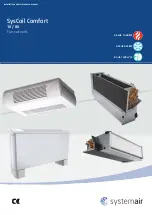
SysCoil Comfort

POWER SUPPLY MUST BE 

SWITCHED OFF 

BEFORE STARTING WORK IN THE 

ELECTRIC CONTROL BOX

1. GENERAL RECOMMENDATIONS

The purpose of this Manual is to provide users with instructions for installing, commissioning, using and 

maintaining the units. It also contains instructions on starting up the machine as well as recommendations 

to avoid bodily injury and risks of damage to the device during its operation.
It does not contain the complete description of all the maintenance operations guaranteeing the unit’s long 

life and reliability. Only the services of a qualified technician can guarantee the unit’s safe operation over a 

long service life.
Please read the following safety precautions very carefully before installing the unit.

1.1. SAFETY DIRECTIONS

Cutoff power supply before starting to work on the appliance.
When making the hydraulic connections, ensure that no impurities are introduced into the pipe work.

The fan-coil units may contain a small amount of oil incompatible with plastic polyethylene piping (PER/

HTA/PVC). The coil should be rinsed out before use to avoid any problem.
It is the installer’s responsibility to contact their pipe supplier and take into account the general instructions 

for the use of plastic pipes. 
The manufacturer declines any responsibility and the warranty becomes void if these instructions are 

not respected.

If you meet a problem, please call the Technical Department of your geographical area.

If possible, assemble the compulsory or optional accessories before placing the appliance on its final location 

(see instructions provided with each accessory).

In order to become fully familiar with the appliance, we suggest to read also our Technical Instructions.

The information contained in these Instructions are subject to modification without advance notice.

1.2. WARNING

Follow the safety rules in forces when you are working on your appliance.

The installation, commissioning, use and maintenance of these units should be performed by qualified 

personnel having a good knowledge of standards and local regulations, as well as experience of this type 

of equipment.

This appliance has not been designed for use by persons (including children) with reduced physical, sensorial 

or mental faculties or by persons without any experience or knowledge of heating systems, unless they act 

under the safety and supervision of a responsible person or have received prior training concerning the use 

of the appliance.
The unit should be handled using lifting and handling equipment appropriate to the unit's size and weight.
Any wiring produced on site must comply with the corresponding national electrical regulations.
Make sure that the power supply and its frequency are adapted to the required electric current of operation, 

taking  into  account  specific  conditions  of  the  location  and  the  current  required  for  any  other  appliance 

connected to the same circuit.
The unit must be EARTHED to avoid any risks caused by insulation defects.
It is forbidden to start any work on the electrical components if water or high humidity is present on the 

installation site.

Содержание SysCoil Comfort SCC10

Страница 1: ...Fan coil units Installation and maintenance manual 84 1 548m3 h 0 53 9 55kW 0 64 13 60kW 10 80 SysCoil Comfort...

Страница 2: ......

Страница 3: ...INSTALLATION INSTRUCTION NOTICE D INSTALLATION INSTALLATIONSHANDBUCH ISTRUZIONI INSTALLAZIONE INSTRUCCIONES DE INSTALACI N English Fran ais Espa ol Deutsch Italiano...

Страница 4: ...0 8 5 INSTALLATION OF THERMOSTAT OR TEMPERATURE SENSOR CHANGE OVER 10 8 5 1 TRM FA 10 8 5 2 TAE20 OR SYSLOGIC 10 8 6 WATER QUALITY 11 9 ELECTRICAL CONNECTIONS 12 9 1 WIRING DIAGRAM AND LEGEND 12 9 2 P...

Страница 5: ...ssible assemble the compulsory or optional accessories before placing the appliance on its final location see instructions provided with each accessory In order to become fully familiar with the appli...

Страница 6: ...e and send immediately a registered letter to the shipper within 48 hours clearly stating the damage caused Forward a copy of this letter to the manufacturer or his representative Never store or trans...

Страница 7: ...g Gg Fuse rating ASE VDE Cable section mini W A A mm SCC10 500 4 10 3G1 5 SCC20 500 4 10 3G1 5 SCC30 500 4 10 3G1 5 1 000 4 10 3G1 5 SCC40 1 250 8 10 3G2 5 2 500 16 16 3G2 5 SCC50 1 250 8 10 3G2 5 2 5...

Страница 8: ...NIT LOCATION Fan coil units are designed to be installed in a controlled environment Each unit should be located on the installation plans Inspect the carton for specific tagging numbers and reference...

Страница 9: ...mentioned Install the fixing screws contractor supply Place the chassis unit on the fixing points and screw it directly to the ceiling or to the veritable support The fan coil unit should be pitched t...

Страница 10: ...ld the casing attached to the two chassis flanks 8 HYDRAULIC CONNECTIONS 8 1 OPERATING FACE The operating face of Left Right versions is defined in relation to the position of the hydraulic connection...

Страница 11: ...CC80 with chilled water coil and heated water coil 1 row on an independent circuit The coil headers are equipped with air vent To vent the air from the coil use the air vent located on the upper part...

Страница 12: ...is at a 90 degree angle between the wall and floor see fluorescent sticker on unit chassis Note If the floor and the wall are not at right angle it may be necessary to shim the fan coil unit to insure...

Страница 13: ...treated or improperly treated water demineralized water salty water or sea water are used Apply the following guidelines No NH4 ammonium ions in the water highly detrimental to copper 10mg l Cl chlori...

Страница 14: ...ysCoil Comfort AC motor TBMV 2P 2P REV 230V 50Hz 60Hz 10 SE 4557 SysCoil Comfort EC motor TBMV 2P 2P REV 230V 50Hz 60Hz 10 9 1 WIRING DIAGRAM AND LEGEND 9 2 POWER SUPPLY The electrical installation mu...

Страница 15: ...w voltage wiring must be done in accordance with electrical code whichever is applicable Earthing of unit is imperative Note if electrical wiring or conduit comes through the floor they must be tight...

Страница 16: ...HERMOSTAT TRM FA 9 5 1 2 1 USE 9 5 1 2 2 USWITCHES 9 5 1 2 3 DIMENSIONS The room thermostat of the air conditioner regulates the room temperature It is designed for closed dry rooms such as flats offi...

Страница 17: ...eed 9 5 1 2 7 FINAL OPERATIONS ADJUSTMENT OF THE TEMPERATURE RANGE The room thermostat is set in the factory for a minimum temperature of 5 C and a max temperature of 30 C Two rings are provided insid...

Страница 18: ...cessible by removing the button 5 4 Maximum temperature setting limiter adjustable by increments of 1 K Mechanical stop accessible by removing the button 5 5 Ambient temperature setting adjustment but...

Страница 19: ...sates actually drain properly installation with or without drainage pump by pouring water into the condensates tray pump electricity supply switched on 10 1 3 VISUAL CHECK 1 Unit mounted as specified...

Страница 20: ...he order confirmation and the unit serial number indicated on the name plate must be provided whenever service works or spare parts are ordered For any spare part order indicate the date of unit insta...

Страница 21: ...onditions Some applications such as hotels where there is a lot of lints from carpeting will require more frequent filter changes If light cannot be seen through the filter when held up to sunlight or...

Страница 22: ...the fluid circulates freely without any sign of leaks or air bubbles 14 1 3 CONDENSATE RECOVERY TRAY 1 Check that the drainage orifices conduits and siphon are not blocked 2 Eliminate all accumulated...

Страница 23: ...APPENDIX ANNEXE ANLAGE ALLEGATO ANEXO APPENDIX ANNEXE ANLAGE ALLEGATO ANEXO...

Страница 24: ...AC CMV VIII SE 4548 SYSCOIL COMFORT MOTOR AC TBMV 4P 2PEH IX SE 4729 SYSCOIL COMFORT MOTOR AC SYSLOGIC X SE 4550 SYSCOIL COMFORT MOTOR EC KLEMMENLEISTE XI SE 4551 SYSCOIL COMFORT MOTOR EC CMV XII SE...

Страница 25: ...C HC Dimensions are in millimeters A B C D E F G H Weight SCC10 240 428 360 189 415 5 61 766 477 20 SCC20 240 428 360 189 415 5 61 766 477 20 SCC30 240 613 360 374 415 5 61 951 477 23 SCC40 240 798 36...

Страница 26: ...A B C D E F G H I Weight SCC10 66 5 428 185 5 189 415 5 61 569 5 430 407 14 SCC20 66 5 428 185 5 189 415 5 61 569 5 430 407 14 SCC30 64 613 184 374 415 5 61 753 430 592 16 SCC40 64 798 184 559 415 5 6...

Страница 27: ...Left 4 pipes Right 2 pipes Left 2 pipes A B C D E F G H SCC10 295 100 337 71 277 139 400 53 SCC20 295 100 337 71 280 164 382 92 SCC30 295 100 337 71 280 164 382 92 SCC40 295 100 337 71 280 164 382 92...

Страница 28: ...t gelieferten Stromlaufplan hinzuziehen ATTENZIONE Questi schemi sono corretti al momento della pubblicazione Le varianti apportate nel corso della fabbricazione possono comportare modifiche Far sempr...

Страница 29: ...HERMOSTAT OPZIONE SCH MONTANA PER TAE20 TERMOSTATO OPCION SCH SUBIDA PARA TAE20 TERMOSTATO AUFGERICHTETE OPTION SCH FUR THERMOSTAT TAE20 M KR RELAIS DE CHAUFFAGE SW SCH SONDE DE TEMPERATURE D EAU KR H...

Страница 30: ...ER SCHUTZ FCA AUTO THERMOSTAT FCM SEGUREZZA MANUALE FCM HANDUBERHITZUNGSSCHUTZ SC HEATING COOLING SELECT SC INVERTITORE CALDO FREDDO SC INVERSOR CALOR FRIO SC UMSCHALTER HEIZUNG KUHLUNG VF KALTWASSERS...

Страница 31: ...si pr sence CF CABLAGE CLIENT Shunt a oter si presencia CF A1 A2 VERKABELUNG KUNDE CABLEADO CLIENTE Shunt in oter if presence CF Config Dip switch Hydronic Valves Mode management 1 2 3 4 5 6 7 O N 1 2...

Страница 32: ...CH ELEMENT S CHAUFFANT S VF MOTEUR DE VANNE TOR VCH MOTEUR DE VANNE TOR FCA SECURITE AUTOMATIQUE 9 10 BU BN BN BU BN BU BK BU BN BN BK BK RD BU OPTION SCH MONTE POUR THERMOSTAT TAE20 MODELE MODEL MODE...

Страница 33: ...NG COOLING SELECT SC INVERTITORE CALDO FREDDO SC INVERSOR CALOR FRIO SC UMSCHALTER HEIZUNG KUHLUNG VF KALTWASSERSCHIEBER WARMWASSERSCHIEBER BK BK BK BK BN BN BK BK BU BK BN BU AVEC RELAIS DE CHAUFFAGE...

Страница 34: ...G KR RELE DI RISCALDAMENTO SB2 FL ANTI INTERFERENCE FILTER FL FILTRO ANTIDISTURBO FL FILTRE ANTIPARASITE BK GY WATER TERMINAL EC Mode management 1 Valves GN WH BN Shunt in oter if presence CF 2 S E 47...

Страница 35: ...TERMOSTATO OPCION SCH SUBIDA PARA TAE20 TERMOSTATO AUFGERICHTETE OPTION SCH FUR THERMOSTAT TAE20 M KR RELAIS DE CHAUFFAGE SW SCH SONDE DE TEMPERATURE D EAU KR HEATER RELAY SW SCH WATER TEMPERATURE SE...

Страница 36: ...TORE CALDO FREDDO SC INVERSOR CALOR FRIO SC UMSCHALTER HEIZUNG KUHLUNG V KALTWASSERSCHIEBER WARMWASSERSCHIEBER BK BK BK BK BN BK BK BN BU AVEC RELAIS DE CHAUFFAGE WITH HEATER RELAY KC BU BK BK BK BU W...

Страница 37: ...L F ALLGENEIMER SCHUTZ F PROTECTION GENERALE Y MOTEUR DE VANNE EAU FROIDE CHAUDE SC INVERSEUR FROID CHAUD SC HEATING COOLING SELECT SC INVERTITORE CALDO FREDDO SC INVERSOR CALOR FRIO SC UMSCHALTER HEI...

Страница 38: ...VALVULA FRIO CALO Y KALTWASSERSCHIEBER WARMWASSERSCHIEBER F GENERAL PROTECTION F PROTEZIONE GENERALE F PROTECCION GENERAL F ALLGENEIMER SCHUTZ F PROTECTION GENERALE Y MOTEUR DE VANNE EAU FROIDE CHAUD...

Страница 39: ...VALVE CHANGE OVER TAE 20 CHANGE OVER TRM FA F CHAUFFAGE ELECTRIQUE VANNE DE REGULATION CHANGE OVER TAE 20 CHANGE OVER TRM FA D ELEKTROHEIZUNG REGELVENTIL CHANGE OVER TAE 20 CHANGE OVER TRM FA I RISCA...

Страница 40: ...2 1 SW 7 8 6 2 L 1 N 2T S S SW TRM FA 3 4 5 6 7 8 9 10 4 N 7 3 2 1 8 6 2 L 1 N 2T S S TRM FA 3 4 5 6 7 8 9 10 4 N 7 3 2 1 8 6 2 L 1 N 2T S S TRM FA 3 4 5 6 7 8 9 10 4 N 7 3 2 1 8 6 2 L 1 N 2T S S TRM...

Страница 41: ......

Страница 42: ...es None As part of our ongoing product improvement programme our products are subject to change without prior notice Non contractual photos Systemair AC SAS Route de Verneuil 27570 Tilli res sur Avre...

Отзывы: