background image

42/48   |   User Manual S-BM2   |   202010

Electrical Connections

IMPORTANT: Danger of electric shock!
Switch off the power supply before working on any electrical equipment.

Only qualified electricians are allowed to work on the electrical system.

Tab. 5: Electric parameters of Belimo mechanism types (B230; B24) for S-BM2 based on the size

Consumption per: Type/ 

In Operation/In Rest/ 

Wire Sizing/Voltage

W

 (mm)

200

250

300

350

400

450

500

550

600

650

700

750

800

850

900

950 1000

H

 (mm)

425

625

825

1025

1225

B24 = 7,5 W/0,5 W/9 VA (AC/DC 24 V)

B230 = 5 W/1 W/12 VA (AC 230 V)

Belimo BLE

B24 = 12 W/0,5 W/18 VA (AC/DC 24 V)

B230 = 8 W/0,5 W/15 VA (AC 230 V)

Belimo BE

NOTE: For Belimo „Bxxx-ST“ versions add 4 W and 10 VA.

Содержание S-BM2

Страница 1: ...S BM2 Smoke Control Damper MA Multi User Manual Fire Safety Products ...

Страница 2: ...stallation Distances 10 Manipulation of S BM2 11 Wet Installation 14 Dry Installation 18 Fit Installation 22 Installation in the Duct Made of Promatect Boards 26 Installation in the Duct Made of Sheet Metal 30 Installation on the Horizontal Duct 34 Installation on the Vertical Duct 38 Electrical Connections 42 Operation Manual 44 Smoke Control Damper Functionality Check 44 Smoke Control Damper Ins...

Страница 3: ... 1396 CPR 0157 Wet Installation Maximum performance up to EI120S Using Plaster Mortar Concrete Filling Dry Installation Maximum performance up to EI120S Using Mineral Wool and Cover Boards NOTE Fire resistivity depends on the type of installation Fit Installation Maximum performance up to EI120S Wall Installation Using Mineral Wool Installation in the Duct Made of Promatect Boards Installation in ...

Страница 4: ...spection in accordance with this User Manual 4 check the damper s functionality as per the Smoke Control Damper Functionality Check chapter before you install the smoke control damper This procedure prevents the installation of a damper that has been damaged during transportation or handling IMPORTANT Do not install non functioning dampers Operating Conditions S BM2 smoke control damper is intende...

Страница 5: ...control damper must be at least 75 mm When the S BM2 smoke control damper is installed into a smoke and fire partition structure it must be placed so that the damper blades in its closed position are located inside this structure The gap in the installation opening between the smoke control damper and the wall ceiling can be increased by up to 50 of the gap area or decreased to the smallest amount...

Страница 6: ...y Fit 200 425 up to 1000 1225 EI90 vew i o S1000 Cmod MAmulti Wall Rigid 125 Flexible 125 EI90 how i o S1000 Cmod MAmulti Floor ceiling EI120 vew i o S1000 Cmod MAmulti Wall Rigid 125 Flexible 125 EI120 how i o S1000 Cmod MAmulti Floor ceiling Dimension Range mm Classification Duct Orientation Applicable Duct Tested per Standard Allowed Blade Axis Orientation In the Duct On the Duct Bottom Mounted...

Страница 7: ...uct Damper placed within the duct canal outside of supporting construction Installation in the duct made of promatect boards Installation in the duct made of sheet metal Installation on the horizontal duct flush with edges Installation on the horizontal duct surface Installation on the vertical duct flush with edges Installation on the vertical duct surface Horizontal blade axis orientation of the...

Страница 8: ...ed as multi multi multi single and single multi Opening Preparation for a Rigid Wall Fig 1 Rigid wall ceiling with a rectangular opening NOTE Dimensions W1 and H1 are defined in every installation Tab 3 Thickness of tested wall Fire Resistivity Minimum s mm Wall Concrete Masonry Cellular Concrete 90 125 10 120 150 10 Legend 1 Concrete Masonry Cellular Concrete s 1 W 1 H 1 ...

Страница 9: ...lasterboards Insulation Thickness Cubic Density mm mm kg m3 90 125 75 B C 12 5 40 50 80 115 120 150 100 C 60 70 85 115 Legend 1 On each side 2 layers of plasterboard fireproof plate type F EN 520 thickness see Tab 4 2 Vertical CW profiles profiles with sCW based on fire resistivity see Tab 4 3 Horizontal UW profiles profile with sCW based on fire resistivity see Tab 4 4 Mineral wool thickness cubi...

Страница 10: ...or multiple crossings through a fire resistive wall the minimum distance between two damper bodies is 200 mm This applies for distances between the damper body and a nearby foreign object crossing the fire resistive wall Damper clearances vary from the type of mechanism and their rotation see Fig 3 Fig 3 Installation distances between damper bodies 200 75 s 200 75 ...

Страница 11: ...ft the smoke control damper with the forklift crane 4 Prepare the opening damper hanger connection surfaces and or filling as per the desired installation type 5 Place the smoke control damper in the opening wall installation or on the opening duct installation 6 Once the smoke control damper has been placed fix the damper to ductwork a For wall installation insert the filling as per desired insta...

Страница 12: ...l damper with the forklift crane NOTE Y2 Cutting plane Fig 7 Prepare the opening damper hanger connection surfaces and or filling as per the desired installation type Place the smoke control damper in the opening wall installation or on the opening duct installation 3 4 5 ...

Страница 13: ...allation insert the filling as per desired installation b For duct installation fix the hangers so that the weight of the damper is supported NOTE Y3 Cutting plane b a Fig 9 Carefully remove the fork Remove the wooden support 6 7 8 9 Fig 10 If the ductwork ends with the damper install a grille or grilles NOTE Y4 Cutting plane Y ...

Страница 14: ...he damper s functional parts which could limit its correct functionality The best way is to cover the functional parts during installation To prevent seepage of the filling material use of boards is recommended First let the plaster or mortar or concrete filling harden and then perform the next steps 4 After the filling hardens remove the duct support from inside of the damper 5 If needed uncover ...

Страница 15: ...Wet 202010 User Manual S BM2 15 48 Fig 11 Wet installation of S BM2 smoke control damper H H 80 40 2 1 3 Y W W 270 40 ...

Страница 16: ...ll aligned on the inside Y5 Cross section of Wet installation in flexible wall ended with grille aligned on the outside Y6 Cross section of Wet installation in rigid wall ended with grille aligned on the outside Y7 Cross section of Wet installation in flexible wall ended with grille aligned on the inside Y8 Cross section of Wet installation in rigid wall ended with grille aligned on the inside Y9 ...

Страница 17: ...Wet 202010 User Manual S BM2 17 48 Y 10 2 5 50 20 H W 4 3 1 6 50 10 10 240 50 12 5 125 Y Y10 Y Y Y H W 20 1 3 50 4 10 10 240 12 5 125 ...

Страница 18: ...gap between the damper and the mounting opening use gypsum boards 7 with screws 8 which fix the gypsum boards to wall 5 All the gaps between gypsum boards and the wall and between gypsum boards and the connected ductwork made of Promatect boards need to be filled with putty for gypsum boards 9 e g Rigips Super 6 Check the functionality of the damper Dimension Range mm Classification Supporting Con...

Страница 19: ...Dry 202010 User Manual S BM2 19 48 Fig 12 Dry installation of S BM2 smoke control damper Y 2 7 1 3 H H 80 40 W W 270 40 ...

Страница 20: ...lexible wall ended with grille aligned on the outside Y6 Cross section of Dry installation in rigid wall ended with grille aligned on the outside Y7 Cross section of Dry installation in flexible wall ended with grille aligned on the inside Y8 Cross section of Dry installation in rigid wall ended with grille aligned on the inside Y9 Cross section of Dry installation in flexible wall ended with gril...

Страница 21: ...Dry 202010 User Manual S BM2 21 48 Y10 Y H W 100 20 50 7 6 8 5 50 10 2 50 9 1 3 10 10 240 50 12 5 125 12 5 Y Y Y Y H W 100 20 50 1 3 4 9 7 8 10 10 240 50 12 5 125 12 5 ...

Страница 22: ...with a density of at least 100 kg m3 thoroughly but in such a way that will not deform the duct 4 All the gaps between the wall and the damper and between wall and the connected ductwork made of Promatect boards need to be filled with putty for gypsum boards 9 e g Rigips Super 5 Check the functionality of the damper Dimension Range mm Classification Supporting Construction Construction Type Minima...

Страница 23: ...Fit 202010 User Manual S BM2 23 48 Fig 13 Fit installation of S BM2 smoke control damper W W 270 H H 80 Y 2 1 3 ...

Страница 24: ... on the inside Y3 Cross section of Fit installation in flexible wall ended with grille aligned on the outside Y4 Cross section of Fit installation in flexible wall ended with grille aligned on the inside Y5 Cross section of Fit installation in flexible wall ended with grille on both sides Legend Y 50 50 1 3 20 H W 6 10 2 50 5 50 10 10 240 50 12 5 125 max 25 15 Y max 25 15 ...

Страница 25: ...Fit 202010 User Manual S BM2 25 48 Y 50 4 1 3 20 H W 50 6 10 2 50 5 10 10 240 50 50 12 5 125 max 25 15 Y max 25 15 Y 20 H W 50 1 3 4 10 10 240 50 12 5 125 max 25 15 ...

Страница 26: ...control damper must remain accessible for maintenance it may be necessary to create additional inspection panels in the connecting ducts The maximum resistivity for in duct installation is EI120S with pressure level 2 1000 Pa 300 Pa Dimension Range mm Classification Supporting Construction Construction Type Minimal Thickness mm Allowed Blade Axis Orientation In the Duct 200 425 up to 1000 1225 EI9...

Страница 27: ...DBH 202010 User Manual S BM2 27 48 Fig 14 Connection of the S BM2 smoke control damper to board made duct X Y ...

Страница 28: ...1 S BM2 accessory Legend Follow the instructions and perform the installation as depicted in the figures and the details section 1 Prepare the duct connection or opening clean and flatten the connecting surface 2 Apply fire resistive coat 6 on the connection surfaces 3 Connect the damper to ductwork 4 From boards 13 create collars and overlap the connection 5 Fix the collar covering to the damper ...

Страница 29: ...DBH 202010 User Manual S BM2 29 48 X 30 H W 6 13 240 50 230 10 5 2 1 Y 5 2 6 1 13 H 20 W 20 30 50 50 240 40 10 Y 50 50 240 H W 40 10 6 1 13 2 5 Y 10 H W 50 50 50 50 50 240 6 1 14 10 2 5 13 ...

Страница 30: ... remain accessible for maintenance it may be necessary to create additional inspection panels in the connecting ducts The maximum resistivity for in duct installation is EI120S with pressure level 2 1000 Pa 300 Pa Dimension Range mm Classification Supporting Construction Construction Type Minimal Thickness mm Allowed Blade Axis Orientation In the Duct 200 425 up to 1000 1225 EI90 ved i o S1000 Cmo...

Страница 31: ...DMH 202010 User Manual S BM2 31 48 Fig 15 Connection of the S BM2 smoke control damper to sheet metal ductwork Y ...

Страница 32: ...m boards 13 create collars and overlap the connection 5 Fix the collar covering to the damper and ductwork with nails or pins as per duct system manufacturer instructions Y1 Cross section of connection with sheet metal ductwork Y2 Cross section of connection with sheet metal ductwork and on one side ended with grille Y3 Cross section of connection to mineral wool insulated sheet metal duct Y4 Cros...

Страница 33: ...DMH 202010 User Manual S BM2 33 48 Y 1 11 10 240 H W 40 Y 240 40 H W 4 1 11 10 Y 50 50 240 10 H W 40 6 11 5 13 10 12 t 1 Y 6 5 11 10 12 10 H W 40 50 240 t 13 1 4 10 ...

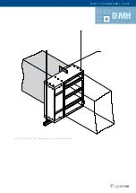
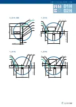
Страница 34: ...ction surfaces must be flattened and clean before the fire resistive coat is applied Suspension systems longer than 1 5 m require fire resistant insulation Dimension Range mm Classification Supporting Construction Applicable Duct Tested per Standard Allowed Blade Axis Orientation On the Duct Bottom Mounted On the Duct Top Mounted On the Duct Side Mounted 200 425 up to 1000 1225 EI90 ved i o S1000 ...

Страница 35: ...Manual S BM2 35 48 D1H D2H Fig 16 Installation of the S BM2 smoke control damper on the horizontal duct flush with edges Fig 17 Installation of the S BM2 smoke control damper on the horizontal duct surface X Y Z X ...

Страница 36: ...r instructions IMPORTANT Dimension of opening must be created according to details of each type and thickness of connected duct The fire resistivity of S BM2 smoke control damper must be decreased to the duct performance The maximum resistivity for D1H D2H installation is EI120S with pressure level 2 1000 Pa 300 Pa X1 Cross section of connection to variable thick board duct ended with grille Y1 Cr...

Страница 37: ...er Manual S BM2 37 48 D1H D2H X D1H D2H 2 13 5 1 4 6 H W 40 10 150 240 30 Y D1H 50 240 H 80 W 80 40 150 4 13 1 10 30 2 6 5 Y D1H 50 50 240 40 H W 4 1 13 2 6 5 10 50 Y3 D2H 35 30 240 H W 10 40 1 4 13 150 35 6 2 5 ...

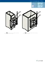
Страница 38: ... of the damper The connection surfaces must be flattened and clean before the fire resistive coat is applied Suspension systems longer than 1 5 m require fire resistant insulation Dimension Range mm Classification Supporting Construction Applicable Duct Tested per Standard Allowed Blade Axis Orientation On the Duct Side Mounted 200 425 up to 1000 1225 EI90 ved i o S1000 Cmod MAmulti Horizontal duc...

Страница 39: ...r Manual S BM2 39 48 D1V D2V X Y Y X Fig 18 Installation of the S BM2 smoke control damper on the vertical duct flush with edges Fig 19 Installation of the S BM2 smoke control damper on the vertical duct surface ...

Страница 40: ...rer instructions IMPORTANT Dimension of opening must be created according details of each type and thickness of connected duct The fire resistivity of S BM2 smoke control damper must be decreased to the duct performance The maximum resistivity for D1V D2V installation is EI120S with pressure level 2 1000 Pa 300 Pa X1 Cross section of connection to variable thick board duct aligned on the outside e...

Страница 41: ...anual S BM2 41 48 D1V D2V X D1V H 80 W 80 40 10 50 240 150 1 4 2 13 5 6 30 X D1V H W 40 10 50 50 240 150 10 50 2 13 5 1 4 6 Y D1V D2V 35 30 240 10 40 H W 1 4 13 150 5 35 6 2 X3 D2V 2 13 5 1 4 6 H W 40 10 150 240 30 ...

Страница 42: ... Electric parameters of Belimo mechanism types B230 B24 for S BM2 based on the size Consumption per Type In Operation In Rest Wire Sizing Voltage W mm 200 250 300 350 400 450 500 550 600 650 700 750 800 850 900 950 1000 H mm 425 625 825 1025 1225 B24 7 5 W 0 5 W 9 VA AC DC 24 V B230 5 W 1 W 12 VA AC 230 V Belimo BLE B24 12 W 0 5 W 18 VA AC DC 24 V B230 8 W 0 5 W 15 VA AC 230 V Belimo BE NOTE For B...

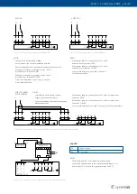
Страница 43: ...t BELIMO actuator S1 S2 S3 S4 S5 S6 3 87 1 N 2 L 3 L AC 230 V B L E 24 12 ST BKNE230 24 4 5 6 7 1 2 3 a b L N 1 2 NOTES The actuator and the control module are factory wired Connect the supply voltage to the connecting cable approx 1 m with ferrules 2 wire cable for signals terminals 6 and 7 1 Supply voltage 2 2 wire cable Legend S1 S2 S3 S4 S5 S6 3 87 1 N 2 3 L1 AC 230 V S1 S2 S3 S4 S5 S6 3 87 1 ...

Страница 44: ...egulations and standards at least once every 3 months The check needs to be performed by an employee who has been specifically trained for this purpose by the manufacturer The current damper condition evaluated during the inspection must be entered into the Operating Journal along with the date of the inspection the legible name surname and signature of the employee who performed the inspection Th...

Страница 45: ...herefore the complete system must be checked as specified in its operational and maintenance requirements 10 Set into the operating position as per the Operation Manual chapter 11 Record the result into the Operating Journal with the name and signature of the Inspection Technician Warranty Conditions For warranty conditions contact your local Systemair representative Functionality of every S BM2 s...

Страница 46: ...e Applied Installation Method with a Cross Wet Dry Fit Date Description of the Discovered Defects and the Date of the Following Inspection after the Elimination of Deficiencies Inspection Technician s Signature In the Duct In the Duct On the Duct On the Duct On the Duct On the Duct ...

Страница 47: ...BM2 47 48 Periodic Damper Inspections at Least Once Every 3 Months Date Description of the Discovered Defects and the Date of the Following Inspection after the Elimination of Deficiencies Inspection Technician s Signature ...

Страница 48: ... EN 12101 8 2011 Smoke control damper Multi compartment S BM2 Nominal activation conditions sensitivity Manual intervention passed Closure opening during test at correct time and in allowable time Response delay closure time Manual intervention passed Operational reliability 10 000 operations 0 to 90 passed 45 to 60 passed Fire resistance Integrity E EI120 vew ved hod i o S1000Cmod MAmulti Damper ...

Отзывы: