44/46 |
FDR-3G…OF
Operation manual
Warning
To avoid injury, make sure to wear gloves and keep the blades movement area clear while manipulating with the
damper.
Fire Damper Functionality Check
Manually Operated Activation Mechanism
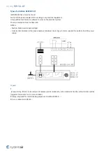
1. Open the damper - turn the red crank (P10) using a hexagon bent wrench No. 10 (P13). Turn the red crank so that
the indicator arrow is pointing to the “OPEN“ position (P11), the red crank needs to remain in the “OPEN“ position,
and the microswitch for the open position indication must be pushed (if installed).
2. Close the damper – release the mechanism by pressing the red release button (P9), the red crank will adjust its
indicator arrow pointing to the “CLOSED“ position (P12) and remain locked in this position, the microswitch for the
closed position indication must be pushed (if installed).
3. Open the damper - turn the red crank (P10) using a hexagon bent wrench No. 10. (P13) Turn the red crank so that
the indicator arrow is pointing to the “OPEN“ position, the red crank needs to remain in the “OPEN“ position, and
the microswitch for the open position indication must be pushed (if installed).
Spring Return Actuator Operated Activation Mechanism
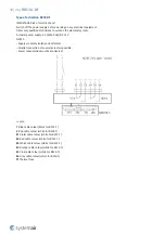
1. The fire damper must open automatically after the actuator circuit closes – the arrow on the actuator axis must
show the position 90°.
2. Press the control switch (P9) on the Thermoelectric fuse and hold it until the fire damper is fully closed – the arrow
on the actuator axis must show the position 0°.
3. Release the control switch on the Thermoelectric fuse. The fire damper must become fully open – the arrow on the
actuator axis must show the position 90° - which is the operating position.
Smoke detector and spring return actuator operated activation mechanism
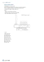
1. The fire damper must open automatically after the actuator circuit closes – the arrow on the actuator axis must
show the position 0°.
2. Press the control switch (P9) on the Thermoelectric fuse and hold it until the fire damper is fully closed – the arrow
on the actuator axis must show the position 90°.
3. Release the control switch (P9) on the Thermoelectric fuse. The fire damper must now open automatically.
4. Press the control switch on the smoke sensor and hold it until the fire damper is fully closed. Or use a smoke spray
for sensor testing and spray into the grille directly onto the smoke detector. Check if the fire damper will fully close.
After a while the smoke detector will clear itself from the testing spray and the damper will open again.
5. Release the control switch on the Thermoelectric fuse. The fire damper must become fully open – the arrow on the
actuator axis must show the position 0° - which is the operating position.
Operation Manual
After installation, it is necessary to adjust the damper into its operating position – open the fire damper.
Spring Return Actuator Operated Activation Mechanism
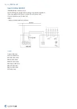
Connect the electric driving mechanism to the relevant electric power supply (see Electrical connection section). The
electromotor is activated and adjusts the damper into its open position.
Manually Operated Activation Mechanism
Turn the red crank into the “OPEN“ position. The damper blade must remain in open position.
Damper Inspection
The activation mechanism keeps the dampers on stand-by during their entire life cycle in accordance with this manual
issued by the manufacturer. It is not permitted to alter the dampers in any way nor perform any changes to their
structure without the manufacturer’s consent.
Содержание A-FDR-3G-OF
Страница 1: ...FDR 3G OF Overflow Fire Damper FDR 3G...
Страница 13: ...13 46 FDR 3G OF 250 DN 630 Standardardly in position B On demand in position L T...
Страница 17: ...17 46 FDR 3G OF...
Страница 18: ...18 46 FDR 3G OF...
Страница 21: ...21 46 FDR 3G OF...
Страница 22: ...22 46 FDR 3G OF...
Страница 25: ...25 46 FDR 3G OF...
Страница 26: ...26 46 FDR 3G OF...
Страница 29: ...29 46 FDR 3G OF...
Страница 30: ...30 46 FDR 3G OF...
Страница 46: ...Systemair DESIGN 2021 04 27 Handbook_FDR_3G_OF_en GB...

