60/64 |
F-B90
Operation Manual
Functionality Check
Before and after you install the damper, make sure that the dampers functionality is checked. The functionality is
checked by:
1. Opening the damper:
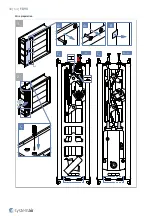
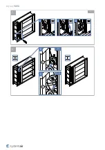
• Remove the Grille (if fitted) and remove the mechanism housing doors by unscrewing bottom and top door screws.
Manual crank activation mechanism:
• Manually open the damper by rotating the metal handle approximately 95° until the indication arrow points to and
remains on "open" symbol.
Note:
You can do it by hand or it is possible to use screw driver shank as a lever by inserting into available handle with
arrow.
Spring return actuator activation mechanism:
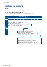
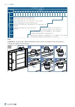
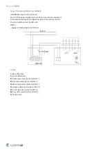
• Connect the actuator to the related electric power supply (refer to the “Electrical connections” section).
• The blade must move to the fully open position. Then, the blade must stay locked. The arrow on the actuator axis
must show the position 90°.
2. Testing the dampers closing ability:
Manual crank activation mechanism:
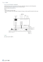
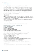
• By pressing the test button (P13). This will close the damper.
Spring return actuator activation mechanism:
• By pressing and holding the test button on the thermal fuse (P13). This will close the damper.
Note:
When you release the test button the actuator will move automatically back to open position.
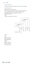
• After the blade is in closed position, the related signaling circuit sets to on. Make sure that wires S4 and S6 are
connected.
3. Put the damper into its operating position - "open":
Manual crank activation mechanism:
• Manually open the damper by rotating the metal handle approximately 95° until the indication arrow points to and
remains on "open" symbol.
Note:
You can do it by hand or it is possible to use screw driver shank as a lever by inserting into available handle with
arrow.
Spring return actuator activation mechanism:
• Connect the actuator to the related electric power supply (refer to the “Electrical connections” section).
• The blade must move to the fully open position. Then, the blade must stay locked. The arrow on the actuator axis
must show the position 90°.
After the installation close the mechanism housing doors and fasten them with screws through bottom and top holes.
Mount the Grille, if previously removed.
Содержание 178818
Страница 1: ...F B90 Multiblade Fire Damper Handbook...
Страница 21: ...21 64 F B90 5 1 1 2 B A1 A2 3 A1 B A2...
Страница 22: ...22 64 F B90 C1 C2 C3 C4 C5 i D 4 1 8 1 Fx D1 D2...
Страница 23: ...23 64 F B90 F3 5 2 E F F3 E1 E2 5 F1 F2 6...
Страница 48: ...48 64 F B90 Wire preparation C1 A1 A2 B C2 C2 H B G A1 A2 B 2 1 C2 C1...
Страница 61: ...61 64 F B90 D1 D2 D3 P13 P13 E E H B G 1 2 H...
Страница 64: ...Systemair DESIGN 2021 08 25 Handbook_F_B90_en GB...

