Level down
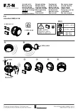
Figure 3-21: Locking and Securing the Eyeball
Table 3-1: Sensitivity versus distance
Distance detector-
reflector ft.
Distance detector-
reflector m
Selected
sensitivity
Attenuation
dB
15 ft to 30 ft.
5 m to 9 m
25% obs.
1.249
30 ft to 70 ft.
9 m to 21 m
30% obs.
1.549
70 ft to 150 ft.
21 m to 46 m
40% obs.
2.218
150 ft to 330 ft
46 m to 100 m
50% obs.
3.010
By locking the eyeball an internal switch is activated and the detector will
now start its initiation or commissioning process. A normal commissioning
process takes roughly 10 seconds. During the commissioning process, the beam
path has to remain clear from object intrusions.
In this process cycle the detector will measure the size of the reflector in its
FOV and determine the distance between detector and reflector. Based on this
measurement, the sensitivity will be automatically set to the optimum
sensitivity for the specific distance.
The process is finalised when the 4 arrows and the middle green LED stop
blinking green. Before going in operational mode, the detector will show its
set sensitivity. This is shown by blinking the 4 arrows to the colour yellow,
reflecting the % of selected obscuration/sensitivity. The key is; 1 blink = 25%,
2 blinks = 30%, 3 blinks = 40% and 4 blinks = 50%.After 5 seconds, the
scenario will be repeated a second time and the arrows LEDs go out and the
front OK LED blinks green. The detector is now in operation and working
correctly.
Completing the Installation
The paintable cover can now be snapped over the front to secure the locking
lever and to hide the alignment LEDS and locking mechanism.
If the cover was painted, ensure that the paint is completely dry before
installing. Mark the set sensitivity on the inside the cover for later use.
Final Verification
1.
Block the entire reflector with an opaque material. Nearly any non-
reflective opaque material will do, including the installation sheet or the
cardboard packaging inserts.
The detector should enter a trouble condition, indicated by the fault relay and
the yellow LED (see
Appendix I. Operation Modes and Troubleshooting
) after 30 seconds. If the detector does not enter a trouble
condition, there is a problem with the installation. Refer to troubleshooting
section in Appendix I. Operation Modes and Troubleshooting Guide OSI-
RIE-xx: for assistance.
2.
Complete by testing the detector using the test filter to create an alarm.
Note:
Before testing, notify the proper authorities that the smoke
detector system is undergoing maintenance, and therefore the
system will be temporarily out of service. Disable the zone or
system undergoing maintenance to prevent unwanted alarms.
Before testing the detector, check for the presence of the flashing green OK
LED at the receiver, making sure not to disturb or block the beam. If it does
not flash and the detector is not in trouble or alarm, power has been lost to the
detector (check the wiring).
Testing and Determining the Sensitivity
of the Unit
Calibrated Test Filter
Testing at the Imager
A quick test can be performed at the imager side by using the acrylic test
filter, OSP-004.
l
Place the filter in front of the imager’s lens. The detector should enter
alarm within 1 minute.
l
The detector can be reset by a command from the FACP.
l
Notify the proper authorities that the system is back on line.
At each reset action, the detector will show its set sensitivity.
After the RED alarm LED is off, the yellow alignment arrows on the front
will indicate the set sensitivity by blinking the arrows yellow to indicate the
set level.
The key is; 1 blink = 25%, 2 blinks = 30%, 3 blinks = 40% and 4 blinks = 50%.
After 5 seconds, the scenario will be repeated a second time.
After this, the detector will now be in normal working condition.
Testing at the Reflector
A thorough test should be performed at the reflector side, see “Testing at the
Imager”. The sensitivity of the detector must be noted during the quick test at
the end of the initial set-up procedure.
1.
The sensitivity of the detector can be verified using the test filter to
cover the reflector. The detector can be reset through a command from
the FACP.
2.
Notify the proper authorities that the system is back on line.
If the detector fails this test several steps should be taken to determine if the
detector is faulty or simply needs to be re-adjusted before returning the unit.
These steps include:
1.
Verify all wiring connections and appropriate power is applied to the
detector.
2.
Verify that the optical line of sight is free from obstructions and
reflective objects.
3.
Apply the maintenance procedure in this manual. Repeat the test
procedure.
4.
If the detector still fails the test procedure proceed with step 4.
5.
Repeat the alignment procedure in this manual. If the alignment
procedure is successful repeat the test procedure. If the detector still
fails the test it should be returned.
Remote Test Station
The detector can be tested remotely using the remote test station.
Follow instructions included with the test station for proper use. See Figure 3-
15 (Remote Test Station) for wiring diagram.
When activating the test, the detector will reduce the power output of the IR
signal to the point where it drops below the automatically set sensitivity at the
detector.
The detector will remain in alarm condition for as long as the test switch is
activated. The detector has to be reset by the reset command from the FACP.
12
E56-6965-000


