


699-41-20.1
-
33 -
6.8
Maintenance of axes with carriages
6.8.1
Lubrication leading-nut axis type DSK and DST, QS_
6.8.1.1
Axis type DSK/DST 120, 200
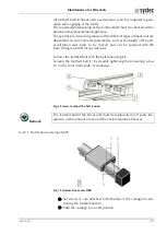
Fig. 24 Lubrication leading-nut
1
Service position
2
Fillister head screws
3
Cover cap
4
Middle slider
5
Set screws
6
Carriage
7
Set screws
8
Cover band
9
Leading-nut receptacle
Drive the carriage to the service position (1).
Remove the fillister head screws (2) and dismount cover cap (3).
Remove the middle slider (4) and unscrew set screws (5).
Push carriage (6) to the side.
Release the set screw (7) and remove it using the sliding nut.
Pull out and lift the cover band (8), now the lubrication hole is
visible in the leading-nut receptacle (9).
Regrease with grease gun. For the quantity of grease see table be-
low.
Attach the dissolved components in reverse order.


