


CONTROL SIGNALS
PAGE
|
44
Command signal
The modulated Command signal applied between Pin 9, PWM Input, and Pin 1, PWM Return, of the User
I/O connector on the ti-Series laser has three basic parameters: signal amplitude, base frequency, and
PWM duty cycle. By changing these parameters, you can command the beam to perform a variety of
marking, cutting, welding, or drilling operations.
The first Command signal parameter, signal amplitude, is either logic low—corresponding to laser beam
off, or logic high—corresponding to beam on. The laser off voltage, typically 0 V, can range from 0.0 V
to +0.8 VDC while the laser on voltage, typically 5 V, can range from +3.5 V to +6.7 VDC.
Base frequency, the second parameter, is the repetition rate of the PWM input signal. The standard base
frequency is 5 kHz, which has a period of 200
μ
s. Maximum PWM frequency is 160 kHz.
The third Command signal parameter, PWM duty cycle, is the percentage of the period that the
Command signal is high. If the Command signal’s amplitude (at 5 kHz) is high for 100
μ
s and low for 100
μ
s, it has a 50% duty cycle; if the amplitude is high for 190
μ
s and low for 10
μ
s, it has a 95% duty cycle.
The following figure illustrates PWM Command signal parameters while the following table lists PWM
signal specifications.
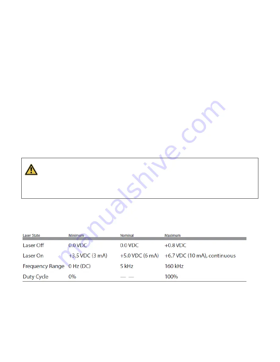
Your user I/O PWM input consists of a high-speed optoisolator LED with a forward voltage drop (Vf) of
1.5 VDC. The PWM input frequency can range from DC (0 Hz) to 160 kHz. the following table provides
minimum, maximum, and nominal PWM signal specifications.
Table 4-3 PWM command signal specifications.
Warning: Serious Personal Injury
Because of phase differences, external tickle pulses may combine with the internally generated tickle
signal causing the LASE LED to flicker during the transition from tickle to lasing. Laser output may
occur if the LASE LED flickers.
Содержание Novanta OEM ti Series
Страница 1: ...ENGINEERED BY SYNRAD OEM ti Series User Manual...
Страница 26: ...TI60 LABEL LOCATIONS PAGE 26 Ti60 label locations Figure 3 1 Ti60 hazard label locations...
Страница 27: ...TI80 LABEL LOCATIONS PAGE 27 Ti80 label locations Figure 3 2 Ti80 hazard label locations...
Страница 28: ...TI100 LABEL LOCATIONS PAGE 28 Ti100 label locations Figure 3 3 Ti100 hazard label locations...
Страница 32: ...EUROPEAN UNION EU REQUIREMENTS PAGE 32 Table 3 1 Class 4 safety features...
Страница 34: ...EUROPEAN UNION EU REQUIREMENTS PAGE 34 Figure 3 4 ti60 Declaration Document...
Страница 35: ...EUROPEAN UNION EU REQUIREMENTS PAGE 35 Figure 3 5 ti80 Declaration document...
Страница 36: ...EUROPEAN UNION EU REQUIREMENTS PAGE 36 Figure 3 6 ti00 Declaration document...
Страница 52: ...USER I O CONNECTION SUMMARY PAGE 52 Figure 4 5 User I O pinouts Table 4 3 User I O pin descriptions continued...
Страница 55: ...INPUT SIGNALS PAGE 55 Table 4 5 Input signal table continued...
Страница 65: ...DB 9 PIN DESCRIPTIONS PAGE 65 Table 4 9 Side mounted DB 9 pin descriptions continued...
Страница 73: ...REMOTE INTERLOCK FUNCTIONS PAGE 73 Table 4 10 Ti60 general specifications continued...
Страница 74: ...REMOTE INTERLOCK FUNCTIONS PAGE 74 Table 4 11 Ti80 general specifications...
Страница 75: ...REMOTE INTERLOCK FUNCTIONS PAGE 75 Table 4 11 Ti80 general specifications continued...
Страница 76: ...REMOTE INTERLOCK FUNCTIONS PAGE 76 Table 4 12 Ti100 general specifications...
Страница 77: ...REMOTE INTERLOCK FUNCTIONS PAGE 77 Table 4 12 Ti100 general specifications continued...
Страница 79: ...TECHNICAL DRAWINGS PAGE 79 Figure 4 26 Fan cooled ti60 ti80 package outline and mounting dimensions...
Страница 82: ...TECHNICAL DRAWINGS PAGE 82 Figure 4 29 Ti Series HS Outline and Mounting...
Страница 83: ...TECHNICAL DRAWINGS PAGE 83 Figure 4 28 Ti 100p Outline and Mounting...
Страница 84: ...TECHNICAL DRAWINGS PAGE 84 Figure 4 29 Ti 100 Fan Outline and Mounting...
Страница 85: ...TECHNICAL DRAWINGS PAGE 85 Figure 4 30 ti Series packaging instructions...
Страница 93: ...MAINTENANCE TROUBLESHOOTING PAGE 93 Table 4 14 Status Signals...
Страница 99: ...MAINTENANCE TROUBLESHOOTING PAGE 99...
Страница 105: ...APPENDIX PAGE 3 This page is intentionally left blank...


