


38
TimeProvider 500 2.0 User’s Guide
098-00172-000 Revision A – December, 2009
Chapter 2 Installation & Configuration
Configuration Setup
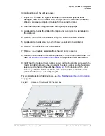
1. Connect a 4 mm² /16 AWG green/yellow striped insulated wire from the
Grounding terminal on the TimeProvider 500 shelf to the Earth Ground on the
rack or cabinet. Connect it to the Earth Ground in accordance with Local
Electrical Codes. The surface of the Earth grounding terminal must be clean of
contaminants and oxidation.
2. Remove 1/4 in. (6mm) of the insulation from the 16 AWG green/yellow stripped
wire and coat the conductor with an electrically conductive antioxidant compound
such as Kopr-shield spray. Spray antioxidant compound on the exposed wire
only.
3. Crimp a #10 (4mm) UL listed Ring Lug to one end of the 16 AWG green/yellow
stripped wire and connect it to the TimeProvider 500 using the 4mm kept nut
supplied. Clamp the Ring Lug between the two flat washers.
4. Clean the connection point on the rack to a bright finish and coat it with an
electrically conductive antioxidant compound such as Kopr-shield spray. Connect
the Ring Lug to the rack or grounding rod following Local Electrical Codes. Do
not connect multiple connectors to the same screw assembly.
5. Crimp the other end of the green/ yellow stripped wire to a ¼ inch (6mm) UL
listed Ring Lug and connect it to the Earth Grounding terminals using an external
star lock washer between the Ring Lug and rack or earthing point to be
grounded.
Configuration Setup
Setting up the TimeProvider 500 requires very few steps, primarily because it uses
auto-negotiation with grandmaster clocks to establish and maintain the PTP flow
(the messages needed for synchronization through the network). Once connectivity
with the intended master clock(s) is established, the synchronization process will
automatically occur. The high-level steps needed are:
Apply power (POWER
A and/or POWER
B) to the TimeProvider 500.
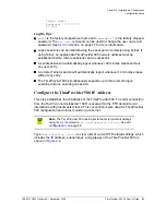
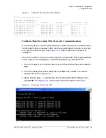
Configure the network address of the TimeProvider 500, and confirm successful
connectivity.
Configure the target address of the grandmaster clock(s) from which the
TimeProvider 500 should synchronize. Verify connectivity.
Verify PTP flow between TimeProvider 500 and grandmaster clock(s)
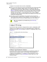
Configure TimeProvider 500 signal output, if needed.
The configuration actions performed in this section are stored in non-volatile
memory and are retained when the unit is power-cycled.
Содержание TimeProvider 500
Страница 10: ...Table of Contents 10 TimeProvider 500 2 0 User s Guide 098 00172 000 Revision A December 2009 ...
Страница 12: ...List of Figures 12 TimeProvider 500 2 0 User s Guide 098 00172 000 Revision A December 2009 ...
Страница 122: ...122 TimeProvider 500 2 0 User s Guide 098 00172 000 Revision A December 2009 Chapter 4 CLI Commands Show Commands ...
Страница 146: ...146 TimeProvider 500 2 0 User s Guide 098 00172 000 Revision A December 2009 T1 Format ...
Страница 174: ...Index W W 174 TimeProvider 500 2 0 User s Guide 098 00172 000 Revision A December 2009 ...


