background image

Chapter 6 

NetBackup 5220 hardware removal and replacement 


111 


To prevent the possibility of installing the replacement PCI add-in card on the 
wrong side of the PCI riser assembly, carefully replace one card at a time. 

14.


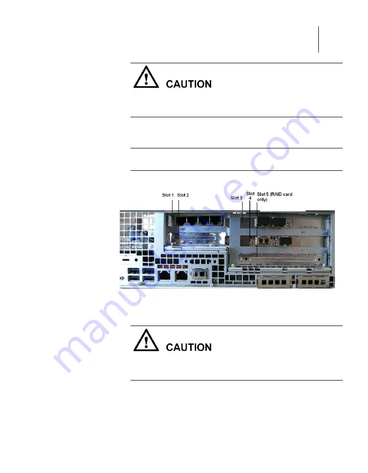
Install the PCI add-in cards into Slot 1 through 4 of the riser card 
assembly. 

Note: You are not allowed to install a PCI add-in card into Slot 5, which is 
reserved for the RAID Controller Card. 

Rear of riser card assembly with slots 1 to 5 


15.


Replace the internal air duct into the chassis. Be sure it aligns 
correctly with the fan module, DIMM slots, CPUs, and side of the 
chassis. 


Do not move or damage any cables or other connectors located near the air 
duct. 

16.


Replace the riser card assembly into the chassis. 

17.


Align the three hooks in the PCI riser assembly with the matching 
slots at the back of the chassis. 

18.


Press down evenly until the three hooks on the rear of the PCI riser 
assembly engage the chassis rear panel slots.  

Содержание NetBackup 5220

Страница 1: ...NetBackup 5220 and Symantec Storage Shelf Hardware Troubleshooting Guide Release 2 0...

Страница 2: ...engineering No part of this document may be reproduced in any form by any means without prior written authorization of Symantec Corporation and its licensors if any THE DOCUMENTATION IS PROVIDED AS IS...

Страница 3: ...ormation Upgrade assurance that delivers software upgrades Global support purchased on a regional business hours or 24 hours a day 7 days a week basis Premium service offerings that include Account Ma...

Страница 4: ...stomer Service is available to assist with non technical questions such as the following types of issues Questions regarding product licensing or serialization Product registration updates such as add...

Страница 5: ...5 Europe Middle East and Africa semea symantec com North America and Latin America supportsolutions symantec com...

Страница 6: ......

Страница 7: ...tBackup 5220 front view 31 NetBackup 5220 rear panel 32 NetBackup 5220 SAS midplane 35 NetBackup 5220 SAS backplane 35 NetBackup 5220 RAID Support 36 NetBackup 5220 Remote Management Module 3 RMM3 43...

Страница 8: ...e cannot be powered on 62 Possible causes 63 Fault Diagnosis 63 Procedure 63 Memory capacity has decreased 64 Symptom 64 Possible Causes 64 Fault Diagnosis 64 Procedures 65 Disk status LED is red 69 S...

Страница 9: ...97 Installing or replacing the RAID card and accessories 97 Removing the chassis cover 98 Removing the PCI Riser Assembly 99 Removing the internal air duct 101 Adding DIMM memory 102 Installing the Ba...

Страница 10: ...6 Procedure 137 Symantec Storage Shelf cover chassis 137 Disk drives 137 Power supply modules 139 I O modules 1 and 2 140 Cables 141 Serial cable 141 SAS cable connection to the NetBackup 5220 141 Pow...

Страница 11: ...ification Statement USA 158 ICES 003 Canada 158 CE Declaration of Conformity Europe 159 VCCI Japan 159 BSMI Taiwan 159 Regulated Specified Components 159 Chapter 11 Appendix C Installation Assembly Sa...

Страница 12: ...assis with cover removed 37 Chassis with air duct 38 Chassis with riser assembly and air duct removed 39 DIMM sockets 40 Battery screw holes on RAID controller card 41 Riser card assembly upside down...

Страница 13: ...cover removed 97 Removing the NetBackup 5220 chassis cover 99 Chassis with cover removed 99 Chassis with air duct 101 Chassis with riser assembly and air duct removed 102 DIMM sockets 103 Battery Back...

Страница 14: ...123 Removing the NetBackup 5220 chassis cover 126 Chassis with cover removed 126 Battery screw holes on RAID controller card 127 Power Supply Modules 128 Removing the NetBackup 5220 chassis cover 130...

Страница 15: ...ents 44 Non hot swappable components 46 2 port 8Gb FC HBA LED descriptions 53 4 port GE NIC LED descriptions 54 2 port 10GE NIC LED descriptions 55 Disk module LED indications 56 Device LED indication...

Страница 16: ...software is included Product version The following table lists the product version related to this document Product Name Product Version NetBackup 5220 2 0 Symantec Storage Shelf 2 0 Intended audience...

Страница 17: ...ubleshooting Guide Software Troubleshooting Guide Safety Guide Maintenance Guide NetBackup 5200 Series documentation The NetBackup 5200 Series documentation has comprehensive software information Feat...

Страница 18: ...menu Each command contains a brief description of the primary function of the command a synopsis and descriptions of each of the options listed in the synopsis The NetBackup appliance shell menu is a...

Страница 19: ...escription 19 Chapter 2 NetBackup 5220 and Symantec Storage Shelf description This chapter describes the main features of the NetBackup 5220 and Symantec Storage Shelf including physical descriptions...

Страница 20: ...s Intel QuickPath Interconnect Intel QPI EVRD11 1 Memory Support for 800 1066 1333 MT s ECC registered RDIMM or unbuffered DIMM UDIMM DDR3 memory Twelve DIMMs across six memory channels three channel...

Страница 21: ...or Video On board Server Engines LLC Pilot II controller with Integrated 2D Video Controller 32 MB DDR2 Memory LAN Two 10 100 1000 ports provided by Intel 82575 PHYs Expansion Capabilities optional Th...

Страница 22: ...rive Activity Diagnostic LEDs Fan Fault DIMM Fault CPU Fault 5V STBY System Status System Identification POST Code Diagnostics Power Supply Up to two 750 W power supply modules Fans Redundant fan modu...

Страница 23: ...elps you identify the components of your device You can also use the reference information provided on the inside of the chassis cover NetBackup 5220 components Letter Description A Rack Handles B1 Ba...

Страница 24: ...ex Bay two additional 2 5 hard drives or tape drives optional K Disk Carriers qty 8 labeled 0 through 7 from left to right Control panel The front right hand side of the NetBackup 5220 contains a cont...

Страница 25: ...operation Flashing green indicates abnormal performance Flashing amber indicates a non critical condition Solid amber indicates a critical or non recoverable condition No light indicates POST is runni...

Страница 26: ...26 Mainboard NetBackup 5220 mainboard components...

Страница 27: ...atus LED H Memory 1 Fan Header I CPU 1 Fan Header J Processor 1 DIMM slots qty 6 K Processor 2 DIMM slots qty 6 L Processor 2 M CPU 2 Fan Header N Memory 2 Fan Header O Bridge Board Connector P Front...

Страница 28: ...28 Letter Component Z SGPIO header AA I O module mezzanine connector 2 BB I O module mezzanine connector 1 CC Serial port B header...

Страница 29: ...Chapter 2 NetBackup 5220 and Symantec Storage Shelf description 29 Configuration jumpers NetBackup 5220 configuration jumpers...

Страница 30: ...3 are jumpered the BIOS settings are cleared on the next reset These pins should be jumpered on 1 2 for normal operation D Password clear J1E8 If pins 2 3 are jumpered admin and user passwords are cle...

Страница 31: ...Bay Tape drive or two fixed 2 5 hard or boot disk drives optional B Slimline Drive Bay not operational with the NetBackup 5220 C 2 5 Hard Disk Drive Bays qty 8 Notes Drive Bay Addresses are 0 7 start...

Страница 32: ...hard drives This bay is located next to the control panel on the front of the device Notes These drives are not hot swappable The system power must be turned off to insert or remove the drives Bezels...

Страница 33: ...Full height PCI Add in Card Slots qty 3 C Upper Power Supply Module D Upper Power Receptacle E Lower Power Receptacle F Lower Power Supply Module G I O Expansion Module optional H Remote Management Mo...

Страница 34: ...rd or similar devices E NIC 1 Ethernet port 1 RJ 45 private network port provides for device management F NIC 2 Ethernet port 1 RJ 45 service network port provides input output access to the device FC...

Страница 35: ...ctor Fan 5 Power Connector Bridge Board Connector Fan 4 Power Connector Fan 3 Power Connector Fan 1 Power Connector Fan 2 Power Connector Backplane Connectors Backplane Connectors NetBackup 5220 SAS b...

Страница 36: ...f a Symantec Storage Shelf is ordered later than the NetBackup 5220 a RAID Controller Card and accessories will need to be ordered and installed separately If the RAID card and its accessories are req...

Страница 37: ...orage Shelf description 37 Removing the NetBackup 5220 chassis cover 7 Remove the chassis cover completely Chassis with cover removed 8 Standing at the rear of the NetBackup 5220 place one hand on eit...

Страница 38: ...38 9 Lift up with both hands 10 Remove the Riser Card Assembly from the device Chassis with air duct 11 Remove the plastic air duct...

Страница 39: ...rage Shelf description 39 Chassis with riser assembly and air duct removed 12 Loosen the clips on both ends of each of the six empty DIMM sockets 13 Remove any plastic spacers from the sockets 14 Remo...

Страница 40: ...rt the bottom edge of the DIMM into the socket 18 When the DIMM is inserted push down on the top edge of the DIMM until the clips snap into place 19 Make sure the clips are firmly in place 20 Repeat f...

Страница 41: ...attery to the card but do not over tighten or over torque the screws 26 Remove the cover plate from Slot 5 of the riser card assembly 27 Turn the riser card assembly upside down Now slot 5 is on the t...

Страница 42: ...equivalent sockets on the mainboard 33 Connect any cables to the newly installed PCI add in card as needed 34 Replace the chassis cover at top rear of the NetBackup 5220 enclosure 35 Slide the cover f...

Страница 43: ...ach left and right mounting rail for the Symantec Storage Shelf is shipped as a unit The front and back of each rail slide apart a few inches to allow for precise fitting into the rack cabinet The bot...

Страница 44: ...vice 16 disk modules Front panel 1 NetBackup 5220 AC power cord qty 2 External device NetBackup 5220 Bezel External device NetBackup 5220 Network cable External device Symantec Storage Device I O modu...

Страница 45: ...Shelf description 45 Device Component Component location Notes Conditions b Completely remove the disk module 2 Do not remove both power supplies at the same time System power must be maintained 3 Do...

Страница 46: ...ol panel Front right panel NetBackup 5220 Chassis cover Top NetBackup 5220 PCI Riser Assembly Rear mid panel NetBackup 5220 RAID card Rear mid panel NetBackup 5220 4 port GE NIC Rear mid panel NetBack...

Страница 47: ...pheral units include fibers network cables external devices such as computers or monitors and power sockets When analyzing alarms first determine the severity and scope of impact Are the alarms critic...

Страница 48: ...48 Troubleshooting processes This section describes general troubleshooting processes Troubleshooting flowchart...

Страница 49: ...20 alarm information and disk drives data for the Symantec Storage Shelf NetBackup 5220 log collection can be obtained via SSH tools from your Windows PC using CLI options Symantec Storage Shelf CLI c...

Страница 50: ...atus indicators This chapter provides information on LED indicators that provide status information for the NetBackup 5220 and the Symantec Storage Shelf NetBackup 5220 LEDs Mainboard LEDs NetBackup 5...

Страница 51: ...e Diagnostic LEDs B System Identification LED C Status LED D Memory 1 Fan Fault LED E CPU 1 Fan Fault LED F CPU 1 DIMM Fault LEDs G CPU 2 Fan Fault LED H Memory 2 Fan Fault LED I CPU 2 DIMM Fault LEDs...

Страница 52: ...operation Flashing green indicates degraded performance Solid amber indicates a critical or non recoverable condition Flashing amber indicates a non critical condition No light indicates POST is runn...

Страница 53: ...it s or 2Gbit s 2 port 8Gb FC HBA LED descriptions 8 Yellow 4 Green 2 Amber Description Off Off Off Power off Off Off On Flashing Data is being transferred at a rate of 2 Gbit s Off On Flashing Off Da...

Страница 54: ...port GE NIC LED descriptions Type Color Status Description ACT Green Flashing The link is normal and data is being transferred Green On The link is normal Off No link LNK Off Data is being transferred...

Страница 55: ...GE network ports for backup NetBackup 5220 2 port 10GE NIC 2 port 10GE NIC LED descriptions Type Color Status Description ACT LNK Green Flashing The link is normal and data is being transferred Green...

Страница 56: ...ch per disk module for a total of 16 sets of LEDs 6 system LEDs showing status of the entire device Disk module LED indications LED name State Description Disk status Green Amber Operation normal Powe...

Страница 57: ...very 2 seconds System off If one IO module is installed If two IO modules are installed I O module LEDs The Symantec Storage Shelf contains two I O modules accessed from the rear panel of the device T...

Страница 58: ...tional at this time I O module Solid green Flashing green Red Not lit Ready n a Starting up Off Note When starting up the Symantec Storage Shelf the primary I O module on the left side of the rear pan...

Страница 59: ...cludes two fans a connector to a main AC power supply on off switch and a status indicator LED Symantec Storage Shelf power module LED Symantec Storage Shelf power supply LED indications Color State I...

Страница 60: ......

Страница 61: ...on methods for troubleshooting NetBackup 5220 Hardware fault types Hardware cannot be powered on or accessed Memory capacity has decreased Disk status LED is red All disks cannot be scanned Fan On Ala...

Страница 62: ...mber indicates a critical or non recoverable condition Flashing amber indicates a non critical condition No light indicates POST is running or the system is off B Power Sleep Continuous green light in...

Страница 63: ...document Procedure Cause 1 The power plug is not inserted properly 1 Reconnect the plug 2 Check the status of the power on alarm indicator If the power on alarm indicator is flashing green power to th...

Страница 64: ...al support 3 If the power is still off contact technical support Memory capacity has decreased This section describes how to troubleshoot the system when the capacity of the memory detected in the ope...

Страница 65: ...ir circulation and cooling You must maintain the arrangement of DIMMs if you remove install or replace DIMMs There are six DIMM slots sockets for each processor CPU Three DIMM slots in each group of s...

Страница 66: ...ser Assembly there must be six DIMMs installed Note It does not matter into which sockets you place the DIMMs they are interchangeable 7 If not enough DIMMs are installed add as many as needed 8 Verif...

Страница 67: ...kets 5 Replace all DIMMs using new unused DIMMs 6 Replace the air duct making sure it fits securely 7 Replace the PCI Riser Assembly making sure the three hooks on the top of the assembly fit securely...

Страница 68: ...cabinet and place it on a level ESD preventive surface 2 Remove the chassis cover 3 Remove the PCI Riser Assembly if it is installed 4 Remove the air duct to access the DIMM sockets 5 Place a DIMM tha...

Страница 69: ...rier and its disk drive are labeled 0 to 7 from left to right All drives are hot swappable Slot 7 is reserved as a spare Slots 0 to 6 are intended for use with RAID cards forming a RAID 6 group Each m...

Страница 70: ...er 4 Replace the disk carrier module into the empty slot 5 Wait for three minutes after inserting a new disk module and then check the disk status LED If the LED is normal the fault is removed If the...

Страница 71: ...m areas 4 Inspect the bay that housed the module for any signs of damage loose parts or other abnormalities 5 Correct any problems 6 Reinsert the disk module s making sure that it fits correctly 1 On...

Страница 72: ...roperly Before troubleshooting execute the shutdown command through the operating system to power off the NetBackup 5220 and peripherals Disconnect the NetBackup 5220 from power sources and all periph...

Страница 73: ...roblems The control panel on the front of the NetBackup 5220 displays fan status If a problem is indicated you can inspect the six fan LEDs after removing the chassis cover A green LED indicates norma...

Страница 74: ...auses Cause 1 The power is not turned on Cause 2 The fan module or the connection cables are not properly connected Cause 3 The cable connecting the mainboard and the power conversion board is not pro...

Страница 75: ...ontinues to show fan faults check other components for further analyses Cause 2 The fan connection cables are not properly connected Before troubleshooting execute the shutdown command through the ope...

Страница 76: ...n LEDs If an LED is green the fault for that fan is removed If the fault persists check other components for further analyses 14 Replace the chassis cover Cause 3 The cable connecting the mainboard an...

Страница 77: ...ED and two fans A green LED indicates normal operation This section describes how to troubleshoot the system when power supply module problems occur Definition The term protection refers to a power su...

Страница 78: ...while the other module s LED is green NetBackup 5220 function is normal although data operate is at risk if the second module fails TBD If both indicators are amber proceed with Cause 2 1 Remove a no...

Страница 79: ...to the device A short circuit voltage overload or power surge can cause self protection Symptom When the device is running it may be powered off incorrectly or inadvertently The control panel and or t...

Страница 80: ...is faulty In this case contact the customer for resolution If the equipment room power is normal the power module is faulty 3 If the power alarm indicator is amber check other components for further...

Страница 81: ...peratures 4 Placing your left thumb on the blue thumbtab slide the cover towards the rear of the device 5 Make sure the clear plastic air duct is undamaged and securely placed over the two CPUs and tw...

Страница 82: ...he ISM monitoring interface Alarm information Classification Type Device Description Overtemperature of the CPU core Temperature CPU Temperature is not critical yet but is approaching the upper limit...

Страница 83: ...the ISM monitoring interface Alarm information Classification Type Device Description Overtemperature of the CPU core Temperature CPU Temperature is not critical yet but is approaching the high end o...

Страница 84: ...ss them in order of severity 3 Follow the instructions below to determine and correct problems Cause 1 Alarm caused by environmental abnormality 1 For alarms caused by environment abnormalities in the...

Страница 85: ...and all programs on any devices are not running If you disconnect devices while programs are running data loss may occur 1 Shutdown the NetBackup 5220 and any peripherals 2 Disconnect the main AC pow...

Страница 86: ...over 8 Remove the chassis cover completely Chassis with cover removed 9 Standing at the rear of the NetBackup 5220 place one hand on either side of the PCI Riser 10 Lift up with both hands 11 Remove t...

Страница 87: ...can see the clear plastic air duct It covers the two processors CPUs and the two sets of 6 DIMM slots The duct helps maintain airflow through the device Chassis with air duct 12 Lift up the plastic a...

Страница 88: ...88 Chassis with DIMMs and DIMM slots DIMM slots detail...

Страница 89: ...emove the six 4Gb DIMMs from their packages 17 Position a DIMM above a socket 18 Align the notch on the bottom edge of the socket with the key in the DIMM socket 19 Insert the bottom edge of the DIMM...

Страница 90: ...y module If the on alarm indicator is green the power supply module is operating normally 2 Reinsert the power cable and check the status of the on alarm indicator If the on alarm indicator flashes gr...

Страница 91: ...upply module configured install the module in the slot dedicated to power supply module 1 6 With two power supply modules install them respectively in the two slots dedicated for power supply modules...

Страница 92: ...utput vents at the front and rear of the chassis respectively are free of debris or blockage 7 After installing the cover if the system alarm location indicator turns off the fault is resolved 8 If th...

Страница 93: ...e sure you have reviewed the NetBackup 5220 Safety Guide for complete and detailed information regarding safety issues that apply to personnel equipment and environment Note When you service the devic...

Страница 94: ...describes the installation of the toolless guide rails of the NetBackup 5220 Procedure 1 Looking at the front of the rack cabinet place the left guide rail on the left post of the rack cabinet 2 Keep...

Страница 95: ...to install a guide rail to the right side of the cabinet Removing and installing the chassis cover This section explains how to remove and re install the chassis cover of the NetBackup 5220 Removing...

Страница 96: ...ain AC power cord and peripheral cables cords from the rear of the NetBackup 5220 3 Wear ESD preventive wrist straps 4 Carefully remove the NetBackup 5220 from the rack cabinet 5 Place it on a grounde...

Страница 97: ...of the NetBackup 5220 enclosure 2 Slide the cover from the rear of the device towards the front Carefully line up both sides of the cover with the sides of the chassis itself Do not allow warping or d...

Страница 98: ...e NetBackup 5220 a RAID Controller Card and accessories will need to be ordered and installed separately If the RAID card and its accessories are required but not installed obtain the necessary items...

Страница 99: ...ment 99 Removing the NetBackup 5220 chassis cover 8 Remove the chassis cover completely Removing the PCI Riser Assembly Chassis with cover removed 9 Standing at the rear of the NetBackup 5220 place on...

Страница 100: ...100 Chapter 6 NetBackup 5220 hardware removal and replacement Installing or replacing the RAID card and accessories 10 Lift up with both hands 11 Remove the Riser Card Assembly from the device...

Страница 101: ...r plastic air duct It covers the two processors CPUs and the two sets of 6 DIMM slots The duct helps maintain airflow through the device Note In most cases you should only need to remove the air duct...

Страница 102: ...ing the RAID card and accessories Chassis with riser assembly and air duct removed Adding DIMM memory 1 Loosen the clips on both ends of each of the six empty DIMM sockets on the mainboard 2 Remove an...

Страница 103: ...on a DIMM above a socket 15 Align the notch on the bottom edge of the socket with the key in the DIMM socket 16 Insert the bottom edge of the DIMM into the socket 17 When the DIMM is inserted push dow...

Страница 104: ...kup Unit BBU 1 Obtain the RAID controller card and Battery Backup Unit BBU 2 Place the battery on the top of the RAID card 3 Line up the three screw holes of the RAID card with those of the battery Ba...

Страница 105: ...Remove the cover plate from Slot 5 on the rear of the riser card assembly Slot 5 on the rear of the PCI Riser Card Assembly 2 Turn the riser card assembly upside down Now slot 5 is on the top of the...

Страница 106: ...the air duct 5 Replace the riser card assembly into the chassis 6 Align the three hooks in the PCI riser assembly with the matching slots at the back of the chassis 7 Press down evenly until the three...

Страница 107: ...ith the sides of the chassis itself Do not allow warping or damage to the cover 12 Reinstall the single screw at the right front of the external chassis 13 Reinstall the NetBackup 5220 into the rack 1...

Страница 108: ...off all peripheral devices connected to the system turn off the system by pressing the power button and unplug the AC power cord from the system or wall outlet Be sure that all devices are off and al...

Страница 109: ...tBackup 5220 chassis cover 8 Remove the chassis cover completely Chassis with cover removed 9 Standing at the rear of the NetBackup 5220 place one hand on either side of the PCI Riser as shown above 1...

Страница 110: ...talling or replacing PCI add in cards 12 Remove the cover plate from Slot 5 on the rear of the riser card assembly Slots 1 to 4 on the rear of the PCI Riser Card Assembly 13 Turn the riser card assemb...

Страница 111: ...reserved for the RAID Controller Card Rear of riser card assembly with slots 1 to 5 15 Replace the internal air duct into the chassis Be sure it aligns correctly with the fan module DIMM slots CPUs an...

Страница 112: ...sis cover from the top rear of the NetBackup 5220 enclosure 22 Slide the cover from the rear of the device towards the front Carefully align both sides of the cover with the sides of the chassis itsel...

Страница 113: ...tween fans 3 and 6 near the front of the chassis backplane The air baffle is located to the left of the chassis as you stand at the front of the device You may need to temporarily remove one or both o...

Страница 114: ...Orient the baffle such that the foam edges of the baffle contact the backplane and the bottom of the chassis 3 Install the baffle making sure the hook on the front of the baffle is inserted into the c...

Страница 115: ...up to eight hot swap 2 5 inch SAS drives Cautions If you install less than eight drives or devices empty drive bays must be occupied by carriers with baffles or with a filler panel provided for drive...

Страница 116: ...ift the drive from the carrier and store the drive in an anti static bag 4 Install a replacement drive as needed 5 If you are not installing a drive place the plastic retention device into the drive c...

Страница 117: ...lacement 117 3 If you do not have a hard drive installed in the other drive bays install the drive blank into the hard drive carrier 4 Install empty hard drive carriers into any remaining empty hard d...

Страница 118: ...ese devices while programs are running data loss may occur 1 Shutdown the NetBackup 5220 and any peripherals 2 Disconnect the main AC power cord and peripheral cables cords from the rear of the NetBac...

Страница 119: ...etBackup 5220 chassis cover 7 Remove the chassis cover completely Chassis with cover removed 8 Standing at the rear of the NetBackup 5220 place one hand on either side of the PCI Riser as shown above...

Страница 120: ...tor 1 on the mainboard Do not remove the filler panel from the second slot If you are using a 2 socket I O module remove both filler panels from the rear of the chassis 12 Locate the I O expansion fil...

Страница 121: ...nel slot s where the filler panels were installed 18 Then attach the I O module to the mainboard connector and standoffs 19 Re install the air duct making sure it fits properly over the two DIMM secti...

Страница 122: ...up 5220 3 Wear ESD preventive wrist straps 4 Carefully remove the NetBackup 5220 from the rack cabinet 5 Place it on a grounded ESD protective surface 6 Remove the screw on the top right hand side of...

Страница 123: ...eplacement 123 Chassis with cover removed 9 Standing at the rear of the NetBackup 5220 place one hand on either side of the PCI Riser as shown above 10 Lift up with both hands 11 Remove the Riser Card...

Страница 124: ...t field replaceable at this time Contact technical support if you have any issues RAID Activation Key and RAID Mini DIMM The Activation key and mini DIMM s are not field replaceable at this time Conta...

Страница 125: ...etBackup 5220 chassis per the following procedure 1 Shutdown the NetBackup 5220 and any peripherals Be sure that all devices are off and no programs are running If you disconnect devices while program...

Страница 126: ...assis cover 7 Remove the chassis cover completely Chassis with cover removed 8 Standing at the rear of the NetBackup 5220 place one hand on either side of the PCI Riser as shown above 9 Lift up with b...

Страница 127: ...e screws Do not over torque or strip the screws 17 If you are install a new battery place it onto the RAID card and secure it with the screws Do not over torque or strip the screws Battery screw holes...

Страница 128: ...connect the main AC power cord and peripheral cables cords from the rear of the NetBackup 5220 3 Wear ESD preventive wrist straps The NetBackup 5220 can be ordered with two power supply modules which...

Страница 129: ...ce individual fans Be sure that the NetBackup 5220 has been properly powered off and no programs or peripherals are running If you disconnect devices while programs are running data loss may occur 1 S...

Страница 130: ...oving the NetBackup 5220 chassis cover 7 Remove the chassis cover completely Chassis with cover removed 8 Standing at the rear of the NetBackup 5220 place one hand on either side of the PCI Riser as s...

Страница 131: ...lacement 131 Chassis with air duct 10 Remove the plastic air duct 11 Remove the blue air baffle from the left side of the chassis 12 Loosen and lift the bridge by releasing the clip at its upper end 1...

Страница 132: ...NetBackup 5220 hardware removal and replacement Replacing a fan module Fans baffles and bridge 14 Carefully remove each of the six connectors between the fans and the mainboard There is one connector...

Страница 133: ...n assembly to secure it into the chassis 20 Connect each of six fan connections to the connectors on the mainboard 21 Replace the fan baffle between fans 3 and 6 22 Resecure the bridge clipping it int...

Страница 134: ...ice into the rack via the rack rails 5 When the device is firmly placed in the rack the rack handles snap into place 6 To remove the rack handles remove the device from the rack 7 Unscrew the two scre...

Страница 135: ...the safety information section in this manual Note When you service the device you must first power down the device through the OS Make sure no programs or peripherals are running Then unplug all per...

Страница 136: ...front of these rails mount on the front of the vertical metal posts of the rack cabinet 2 Facing the rack cabinet align the left rail over the vertical metal post on the left side of the rack Be sure...

Страница 137: ...that the Storage Shelf sits properly and all screws are secure Symantec Storage Unit rack handles Symantec Storage Shelf cover chassis The Symantec Storage Shelf chassis should not be opened The only...

Страница 138: ...wrist strap 2 Press the disk module release button of the disk drive you want to remove 3 Slide the disk module out of its disk bay 4 Place a new disk module into the empty disk bay 5 Slide the disk m...

Страница 139: ...ered off and no programs or peripherals are running If you disconnect devices while programs are running data loss may occur To remove and replace a power supply module 1 Power the device down 2 Disco...

Страница 140: ...ondary module Both modules are located in the rear of the storage shelf I O module 1 is on the left side of the device I O module 2 is on the right side of the device Symantec Storage Shelf I O module...

Страница 141: ...h the DB9 end of the serial cable to a serial port on the your management PC or server SAS cable connection to the NetBackup 5220 The NetBackup 5220 and Symantec Storage Shelf communicate via one or t...

Страница 142: ...e NetBackup 5220 Power cable Use the two power cords shipped with the Symantec Storage Shelf 1 5m 4 9 ft power cords qty 2 One power cord is provided for each of the two power supply modules in the st...

Страница 143: ...in the rack cabinet 2 The devices can be connected while the power is on It is recommended that both devices are plugged into two AC power sources to maintain redundancy 3 Connect one SAS cable to th...

Страница 144: ...ted up the power disk module controller module and power supply LEDs become green The heartbeat LED blinks green once every 4 seconds if one I O module is installed or once every 2 seconds if two I O...

Страница 145: ...A separate command is not required To clear all link error counts At the cli prompt type link a clear and press Enter cli link a clear Q Can I hot swap a failed drive with a new drive A Yes Disk driv...

Страница 146: ...AC current Max rate input AC current Voltage 110 90Vrms 100 127 Vrms 140 Vrms 85 VAC 5 VAC 75 VAC 5VAC 12Arms 1 11 0Arms3 Voltage 220 180 Vrms 200 240 Vrms 264 Vrms 6 0Arms 2 5 5Arms 3 Frequency 47Hz...

Страница 147: ...ing 90 relative humidity non condensing at 28 C Shock Operating Packaged Unpackaged 2 0 g peak 11 msec half sine Non palletized free fall in height 24 40 lbs to 80 lbs Operational after an 18 free fal...

Страница 148: ......

Страница 149: ...noncompliance with product regulations in the region s in which the product is sold To help ensure EMC compliance with your local regional rules and regulations before computer integration make sure t...

Страница 150: ...tial alarm systems test equipment etc other than an ITE application may require further evaluation Product Safety Compliance UL60950 CSA 60950 USA Canada EN60950 Europe IEC60950 International CB Certi...

Страница 151: ...eshold limits and banned substances are noted below Quantity limit of 0 1 by mass 1000 PPM for Lead Mercury Hexavalent Chromium Polybrominated Biphenyls Diphenyl Ethers PBB PBDE Quantity limit of 0 01...

Страница 152: ...ogy Declaration International China RoHS Environmental Friendly Use Period Packaging Product Recycling Marks Product Regulatory Compliance Markings The NetBackup 5220 product is provided with the foll...

Страница 153: ...device may not cause harmful interference and 2 This device must accept any interference received including interference that may cause undesired operation EMC Marking Class A Canada CANADA ICES 003 C...

Страница 154: ...ry Compliance Markings Belarus Safety Compliance Mark Belarus Waste of Electronic and Electrical Equipment Recycling Mark Europe China Restriction of Hazardous Substance Environmental Friendly Use Per...

Страница 155: ...te Materials This product may include a battery which contains Perchlorate material Safety Multiple Power Cord Marking This unit has more than one power supply cord To reduce the risk of electrical sh...

Страница 156: ...isconnection The AC power cord s is considered the main disconnect for the device and must be readily accessible when installed If the individual device power cord s will not be readily accessible for...

Страница 157: ...German Institute of Electrical Engineers certified cord with 3 x 0 75 mm conductors rated 250 VAC Volts Alternating Current Connector wall outlet end Cords must be terminated in grounding type male p...

Страница 158: ...rease the separation between the equipment and the receiver Connect the equipment to an outlet on a circuit other than the one to which the receiver is connected Consult the dealer or an experienced r...

Страница 159: ...latory certifications and or declarations the following regulated components must be used and conditions adhered to Interchanging or use of other components will void the UL listing and other product...

Страница 160: ...let or power supply The power cord s is considered the disconnect device to the main AC power The socket outlet that the system plugs into shall be installed near the equipment and shall be easily acc...

Страница 161: ...eatsink may be hot if the system has been running Also there may be sharp pins and edges on some board and chassis parts Contact should be made with care Consider wearing protective gloves Danger of e...

Страница 162: ...MEN Immer wenn Sie die Geh useabdeckung abnehmen um an das Systeminnere zu gelangen sollten Sie folgende Schritte beachten 1 Schalten Sie alle an Ihr System angeschlossenen Peripherieger te aus 2 Scha...

Страница 163: ...lie en Sie diese um ein unerlaubtes ffnen des Systems zu verhindern 5 Schlie en Sie alle externen Kabel und den AC Stromanschlu stecker Ihres Systems wieder an Der Mikroprozessor und der K hler sind m...

Страница 164: ...tension hors tension du panneau avant n teint pas l alimentation CA du syst me Pour mettre le syst me hors tension vous devez d brancher chaque c ble d alimentation de sa prise C est le c ble d alime...

Страница 165: ...bles externes au syst me Le microprocesseur et le dissipateur de chaleur peuvent tre chauds si le syst me a t sous tension Faites galement attention aux broches aigu s des cartes et aux bords tranchan...

Страница 166: ...equipo y ser de f cil acceso INSTRUCCIONES DE SEGURIDAD Cuando extraiga la tapa del chasis para acceder al interior del sistema siga las siguientes instrucciones 1 Apague todos los dispositivos perif...

Страница 167: ...e tener en cuenta que en el chasis o en el tablero puede haber piezas cortantes o punzantes Por ello se recomienda precauci n y el uso de guantes protectores Existe peligro de explosi n si la pila no...

Страница 168: ...ositivi periferici collegati al sistema 2 Spegnere il sistema usando il pulsante spento acceso dell interruttore del sistema 3 Togliere tutte le spine dei cavi del sistema dalle prese elettriche 4 Ide...

Страница 169: ...le in sospensione a parte la normale polvere presente nell ambiente Ben ventilata e lontana da fonti di calore compresa la luce solare diretta Al riparo da urti e lontana da fonti di vibrazione Isolat...

Отзывы: