background image

19

Instrucciones de ensamblaje para PB 9210/

Instructions d’assemblage PB 9210

Alinee los bordes de las patas de 
4" x 4" con los bordes de la
abrazadera para EZ Frame
Alignez les bords des pattes de
4 x 4 po (100 x 100 mm) avec ceux
du connecteur EZ Frame

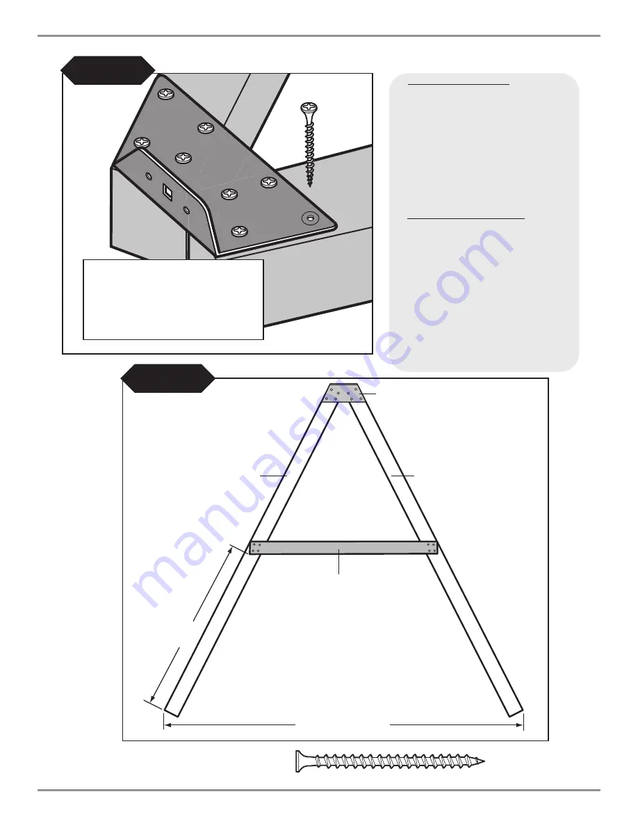
Fig. 8

(8) Tornillos de 2-1/2"

(8) Vis de 2 1/2 po (63 mm)

Tornillo de 2-1/2"

Vis de 2 1/2 po (63 mm)

94-1/2"

94 1/2 po (239 cm)

47-3/4"

47 3/4 po

(121 cm)

Abrazadera del marco en EZ 
Connecteur EZ Frame

4" x 4" x  96''
4 x 4 x 96 po

(100 mm x 100 mm x 244 cm)

2" x 4" x 47-1/2" 

2 x 4 x 47 1/2 po

(100 mm x 100 mm x 121 cm)

4" x 4" x  96''
4 x 4 x 96 po
(100 mm x 100 mm x 244 cm) 

(4)

Tornillos de 2-1/2"

(4)

Vis de 2 1/2 po (63 mm)

(4)

Tornillos de 2-1/2"

(4)

Vis de 2 1/2 po (63 mm)

Fig. 8a

Montaje del marco en “A”

1. 

Coloque las piezas de 4" x 4" como se muestra en
la

(Fig. 8)

.

2. 

Alinee la abrazadera de marco EZ con la parte
frontal de las piezas de 4" x 4".

3. 

Asegure las abrazaderas del marco EZ con (8)
tornillos de 2-1/2" a las piezas de 4" x 4" y
asegúrese de que queden al ras entre sí.

4. 

Asegure la pieza de 2" x 4" a las piezas de 4" x 4"
como se muestra en la

(Fig. 8a)

.

5. 

Dé vuelta y agregue una segunda abrazadera.
Repita los pasos 2 y 3.

Assemblage du cadre en « A »

1. 

Disposez les pièces de 4 x 4 po
(100 mm x 100 mm) tel qu’illustré à la 

(Fig. 8)

2. 

Alignez le connecteur EZ Frame avec la face des
membrures de 4 po x 4 po (100 mm x 100 mm).

3. 

Fixez solidement le connecteur EZ Frame à l'aide de
(8) vis de 2 1/2 po (63 mm) aux membrures de
4 po x 4 po (100 x 100 mm) en vous assurant que
celles-ci sont au niveau les unes par rapport aux autres.

4. 

Fixez les membrures de 2 po x 4 po (50 x 100 mm)
aux 4 po x 4 po (100 x 100 mm) comme illustré à la

(Fig. 8a)

.

5. 

Retournez l’assemblage et ajoutez un 2e connecteur.
Répétez les étapes 2 et 3.

Содержание PB 9210

Страница 1: ...slide com or call us at 1 800 888 1232 ASSEMBLY INSTRUCTIONS No of Children Up to 8 Min Use Zone 26 x 29 Set Dim 14 W x 15 L x 11 H Est Building Time 6 8 hr Minimum Use Zone check out http www swing n slide com planupdates htm for updates to these instructions 26 29 SLIDE AND 4 x 4 LUMBER SOLD SEPARATELY ...

Страница 2: ...in a manner other than intended Not to get off equipment while it is in motion Not to climb on the equipment when it is wet Be sure to go down slides feet first Determined that only one child per planned occupant seat should be allowed on this set at one time Determined children must be dressed appropriately for play Avoid hooded jackets bicycle helmets clothing with draw strings and loose fitting...

Страница 3: ...D WARRANTY Swing N Slide warrants its No Cut and Wood Complete Ready to Assemble Play Set kits against wood rot and termite damage and to be free from defects in workmanship and materials under normal use and conditions for a period of 5 years for structural wood components Cosmetic defects that do not affect the structural integrity of the product or natural defects of wood such as warping splitt...

Страница 4: ...anhead screws 206 2 1 2 screws 34 1 1 2 screws 54 2 lag screw 2 Loc Nuts 4 5 16 Hex Head Lag Screws ELECTRIC DRILL HAMMER TAPE MEASURE SAFETY GLASSES DUST MASK CARPENTER S SQUARE TOOLS REQUIRED 4 64 1 1 4 Lag Screw 2 5 16 x 3 1 2 Hex Head Bolt 8 T Nut 6 Tarp Washers 6 3 4 Pan Head Screw 2 Fence Staple ...

Страница 5: ...Bit 2 EZ Frame Brackets PB 9210 Plan 1 T20 Torx Bit 2 Shelf Loc 6 Wrap Loc 2 Split Beam bracket 1 3 8 DRILL BIT 5 Min 5 6 Step Brackets 2 L Brackets 8 2 x 4 Shelf Loc 2 Boomerang Brackets 6 Slotted Beam Clamp 1 Eye Strap ...

Страница 6: ...DUCT IS INTENDED FOR USE BY CHILDREN FROM AGES 2 10 YEARS For Home Residential Use ONLY 1212 Barberry Drive Janesville WI 53545 1 800 888 1232 www swing n slide com R 1 Name Plate with Hardware 1 Climbing Rope 150 lb Weight Limit 2 Swing Seat weight limit 115 lbs 1 Ring Trap Combo 1 Canopy 6 Swing Hangers 4 Metal Rungs ...

Страница 7: ... x 12 1 4 x 4 x 120 PB 9210 Board List PB 9210 Assembly Instructions English Metric Cm English Metric Cm 1x4 2 5x7 6 3 4x3 1 2 1 9x9 1x6 2 5x15 3 3 4x5 1 2 1 9x14 5 4x4 3 2x10 2 1x3 1 2 2 5x9 5 4x6 3 2x15 3 1x5 1 2 2 5x14 2x2 5x5 1 1 2x1 1 2 3 8x3 8 2x3 5x7 6 1 1 2x2 1 2 3 8x6 4 2x4 5x10 1 1 2x3 1 2 3 8x9 2x6 5x15 3 1 1 2x5 1 2 3 8x14 3x3 7 6x7 6 3 x3 4x4 10x10 3 1 2x3 1 2 9x9 Estim ated Sizing Du...

Страница 8: ...elect the correct fastener Use these 2 pictorial guides to help select the correct fastener s for the lumber attachment you are making Each diagram will highlight the correct number of fasteners to use and where to attach them 5 4 x 4 to 4 x 4 5 4 x 4 to 5 4 x 4 PB 9210 Assembly Instructions 8 NOTE All hardware to be driven until flush with surface of wood or no deeper that 1 16 ...

Страница 9: ...RE INSTRUCTED DO NOT FILL EVERY HOLE IN BRACKET THIS WILL LEAD TO HARDWARE SHORTAGES Top of bracket Example of a Shelf Loc bracket connection Wrap Loc Shelf Loc Bracket 1 2 3 4 Wrap Loc CORRECT WRONG Brackets Clip Together brackets NOT interlocked Brackets clipped Example of a Shelf Loc bracket connection TOP Look for TOP stamp on bracket for correct orientation DO NOT USE LAG SCREWS HERE Use Lag ...

Страница 10: ... 96 4 x 4 x 96 4 x 4 x 96 47 86 Use a 2 lag screw to hold bracket in place for later use Look for TOP stamp on brackets while installing TOP GAP on this side Frame 1 Frame 2 2 1 1 4 Lag Screws per joint Fig 1b DO NOT USE LAG SCREWS HERE Use Lag Screws Only Where Brackets Attach 2 1 1 4 lag screws per bracket 2 1 1 4 lag screws per bracket 2 Lag screw WRAP BRACKET GAP WRAP BRACKET GAP ...

Страница 11: ...s at least 3 4 from edge 2 1 2 screw 5 4 x 4 x 32 2 Lag screw 11 PB 9210 Assembly Instructions 2 x 4 x 32 2 x 4 x 32 5 4 x 4 x 32 5 4 x 4 x 40 5 4 x 4 x 40 4 4 Frame 2 4 x 4 x 32 1 1 4 Lag screw 3 2 1 2 screws per joint 3 2 1 2 screws per joint 3 2 1 2 screws per joint 3 2 1 2 screws per joint 4 2 lag screws per joint NOTE Upper screws are 2 1 1 4 Lag Screws Lower screws are 2 2 Lag Screws Fig 2b ...

Страница 12: ... 3a through Fig 3b Fig 3a Fig 3 2 1 2 screw NOTE Upper screws are 2 1 1 4 Lag Screws Lower screws are 3 2 Lag Screws Fig 3b 2 1 1 4 Lag 3 2 Lag 2 Lag screw 1 1 4 Lag screw 2 1 1 4 lag screws and 3 2 lag screws per bracket 3 2 1 2 screws per joint 3 2 1 2 screws per joint 2 x 4 x 47 1 2 2 x 4 x 47 1 2 5 4 x 4 x 47 1 2 5 4 x 4 x 47 1 2 2 1 1 4 lag screws and 3 2 lag screws per bracket Frame 1 Frame ...

Страница 13: ... 1 Attach deck boards as shown in Fig 4 2 Attach slide support board as shown in Fig 4a 2 1 2 screw 1 1 2 screw 2 2 1 2 screws per joint 2 5 4 x 4 x 24 3 4 10 5 4 x 4 x 32 NOTE 1 2 Gap Between Boards is Typical 5 4 x 4 x 18 11 1 4 4 1 1 2 screws UNDERDECK VIEW ...

Страница 14: ...and Barrier Supports 1 Attach roof support boards as shown in Fig 5 2 Attach barrier support boards as shown in Fig 5a Fig 5a Fig 5 2 1 2 screw 3 2 1 2 screws per joint 5 4 x 4 x 47 1 2 5 4 x 4 x 47 1 2 5 4 x 4 x 32 3 2 1 2 screws per joint ...

Страница 15: ...8 Hole S w i n g B e a m TOP VIEW Fig 6 A FRAME ATTACHES HERE Swing Beam Drill Locations 1 Use a 3 8 drill bit to drill a 3 8 hole through the beam at each location shown in Fig 6 2 Install Swing Hangers onto swing beam at locations shown Note Swing Hangers must be installed on the same side dimensions were originally measured and marked ...

Страница 16: ... the beam and thread it into the T nut until it is flush or near flush with the top of the T nut A screwdriver may be used to twist the hanger Fig 7 Orient swing hanger as shown in Fig 7 4 Step 4 Use 4 1 1 4 screws to secure beam clamp 5 Check hanger to ensure it does not spin 6 Repeat for all swing hangers 4 1 1 4 screws Swing Hanger Use Screwdriver to aid in tightening Bottom Beam Clamp t nut Ha...

Страница 17: ... x 4 x 96 2 x 4 x 47 1 2 4 x 4 x 96 4 2 1 2 screws 4 2 1 2 screws Fig 8a A Frame Assembly 1 layout 4 x 4 s as shown in Fig 8 2 Allign EZ Frame Bracket with face of 4 x 4 s 3 Secure EZ Frame Bracket with 8 2 1 2 screws to 4 x 4 s making sure they are flush with each other 4 Secure 2 x 4 to 4 x 4 s as shown in Fig 8a 5 Flip over and add 2nd bracket Repeat steps 2 and 3 ...

Страница 18: ... Cantilever beam T nut 2 1 2 screws Hex Bolt Washer A Frame Assembly cont 1 Attach A Frame beam to Swing Beam using 2 hex bolts and 4 screws as shown in Fig 9 2 Tighten hex bolt to flush with top of T nut Repeat steps 1 2 on second bracket Fig 9 ...

Страница 19: ...screw x 8 each bracket A Frame Assembly cont 1 Position Split Brackets on 4 x 4 x 47 1 2 Fig 10 2 With the help of others lift A Frame and Swing Beam Assembly and center onto unit as shown in Fig 10 3 Secure as shown in Fig 10a Fig 10 Swing Beam Swing Beam 14 1 4 ...

Страница 20: ...upport Boards 1 Install barrier support boards as shown in Fig 11 and Fig 11a Fig 11a Fig 11 2 1 2 screw 3 2 1 2 screws per joint 2 x 4 x 47 1 2 5 4 x 4 x 47 1 2 2 x 4 x 32 3 2 1 2 screws per board 80 2 5 4 x 4 x 12 2 5 4 x 4 x 12 23 1 2 23 1 2 ...

Страница 21: ...Note There will be a 1 1 4 gap between the deck and the bottom of the barrier boards as shown in Fig 12b 2 1 2 screw 2 1 1 2 screws per joint 2 2 1 2 screws per board 2 1 1 2 screws per board NOTE 2 Gap Between Boards is Typical 3 5 4 x 6 x 44 23 1 2 2 5 4 x 6 x 28 3 4 Fig 12 Fig 12a Fig 12b 1 1 4 Gap Typ 1 1 2 screw ...

Страница 22: ...There will be a 1 1 4 gap between the deck and the bottom of the barrier boards as shown in Fig 13a 2 Install decorative Angle Cut boards as shown in Fig 13b Fig 13b Fig 13 23 1 2 2 1 1 2 screws per joint 2 5 4 x 6 x 28 3 4 2 1 1 2 screws per joint 2 5 4 x 4 x 16 1 4 Angle Cut Fig 13a 1 1 4 Gap Typ 1 1 2 screw ...

Страница 23: ...x 4 x 28 1 2 5 4 x 4 x 28 1 2 22 1 1 2 screw Roof Assembly 1 Assemble the Tarp Support Frame as shown in Fig 14 2 Install Tarp Support Frame as shown in Fig 14a NOTE Mount Tarp Support Frame 1 above flush with Support Boards 3 Install Tarp as shown in Fig 14b and Fig 14c 3 1 1 2 Screws per joint 1 NOTE Mount Tarp Support Frame 1 above flush with Support Boards ...

Страница 24: ...emble Rock Wall as shown in Fig 15 2 Mark locations of Climbing Rocks on the Rock Wall in a pattern that will easily allow your child to climb to the deck Make sure the bolt hole locations are clear of wall supports before drilling 3 Drill holes through the wall at the desired locations using a 3 8 drill bit Install Climbing Rocks as shown in Fig 15a 4 Make sure the Rock Wall and Climbing Rock con...

Страница 25: ...own in Fig 16a 3 Measure and place Monkey Bar Steps on 4 x 4 boards as shown in Fig 16b Fig 16 Fig 16a Fig 16b 1 1 4 Lag screw 2 1 1 4 Lag Screws per rung 6 1 1 4 Screws per bracket 2 x 4 x 47 1 2 2 x 4 x 47 1 2 3 2 x 4 x 23 1 1 4 11 3 4 11 3 4 11 3 4 FLUSH FLUSH 4 x 4 x 96 4 x 4 x 96 FLUSH 26 37 48 3 1 1 4 Lag Screws per rung FLUSH 1 1 4 screw 48 1 2 37 1 2 26 1 2 ...

Страница 26: ...s shown in Fig 17 2 With the help of others position the finished assembly to the unit Fig 17a Determine post locations Remove assembly and dig two 16 deep holes at the previously determined spots as shown in Fig 17b Reposition assembly to unit placing posts in the holes 3 Level the assembly and attach to the unit using six 1 1 4 Lag screws per bracket Fill in holes and compact earth around posts ...

Страница 27: ...or stake 2 Drive wood stake into ground leaving 2 exposed 3 Secure the slide bottom to the stake using 2 1 1 4 deck screws Fig 18a 4 Attach slide to unit as shown in Fig 18 2 Above Ground 2 1 1 4 screws per joint 5 4 x 4 x 17 Fig 18a Use truss head screws to secure slide to deck 3 1 Truss Screw 1 1 4 screw ...

Страница 28: ...roximately 1 apart Wrap the rope under the 5 4 x 6 Then thread the rope through both staples Double the rope back on itself and through the first staple Pull the rope tight and secure in place by pounding staples in place See Fig 19 3 Once you have Secured end of climbing rope cut off any excess with a sharp knife or scissors Fig 19a 1 1 5 4 x 6 x 25 Fig 19b 2 x 4 x 32 2 2 Lag Screws Eye Strap Fig...

Страница 29: ...fety Handle 1 Mount Safety Handle in the Rock Wall opening approximately 11 above the deck surface Fig 21 Fig 21 Deck Surface Safety Handle Swing Barrier Swing Beam Guard 1 Attach Swing Beam Guard board as shown in Fig 20 2 1 2 screw 3 2 1 2 screws per joint 5 4 x 4 x 32 24 Fig 20 11 ...

Страница 30: ... of harness with hooks on a hard surface and force hooks closed with a hammer or squeeze closed with a pliers until parts are touching WARNING Open hooks can cause deep cuts 3 Hang the chains from the nylon bushing swing hangers Crimp the hook opening closed with a pliers to secure the chains to the swing hangers Fig 22c Make sure all connections are tightly crimped and secure before using swing s...

Страница 31: ...tivity center 2 Place the Anchor It stakes adjacent to the base and near the corners of your activity center at the bottom of the legs on swing sets and twist the auger style stakes into the ground until only the loop is exposed 3 Place the metal strap through the loop of the Anchor It stake and secure it to the unit with a lag screw and washer as illustrated to the right Note Attach the strap to ...

Страница 32: ... PlayCore Inc 2010 Printed In USA LA 6240 Questions Call our Customer Service Department at 1 800 888 1232 ...

Страница 33: ... alto Tiempo estimado de construcción 6 a 8 horas Nbre d enfants jusqu à 8 Zone d utilisation minimale 26 pi x 29 pi 7 92 x 8 84 m Dim de l ensemble 14 pi 4 27 m L x 15 pi 4 57 m P x 11 pi 3 35 m H Durée du montage estimée 6 à 8 heures Zona de uso mínimo Zone d utilisation minimum Consulte http www swing n slide com planupdates htm para ver las actualizaciones de estas instrucciones Visitez le htt...

Страница 34: ...ar ni caminar sobre la parte superior de las vigas de los columpios los pasamanos o el techo No usar los equipos de manera diferente a aquella para la cual fueron diseñados No saltar de los equipos cuando están en movimiento No subirse a los equipos cuando estén mojados Asegurarse de bajar por los toboganes con los pies por delante Ha determinado que sólo se puede permitir un niño por asiento en u...

Страница 35: ...ión de Swing N Slide Piezas que se han modificado alterado o usado indebidamente Piezas que no se han usado según su diseño u objetivo Daño debido a hechos de la naturaleza vandalismo uso anormal o abuso según lo determine Swing N Slide Para obtener información adicional sobre seguridad en las zonas de recreo la Comisión de Seguridad para los Productos de Consumo Consumer Product Safety Commission...

Страница 36: ...s prévues Ne pas descendre de l équipement lorsqu il est en mouvement Ne pas grimper sur l équipement lorsqu il est mouillé Veiller à descendre les pieds devant Vous assurer qu un seul enfant à la fois par siège doit être permis sur cet équipement Déterminer le type de vêtements à porter par les enfants pour jouer de façon sécuritaire Éviter les vêtements avec des cordons et des capuchons les casq...

Страница 37: ...és dans des conditions et pour un usage normaux pour une période de cinq 5 ans GARANTIE LIMITÉE DE CINQ 5 ANS DU FABRICANT Swing N Slide garantit les composants structurels en bois de ses ensembles et accessoires de jeu sans coupe et tout bois contre les dommages causés par la pourriture et les termites et contre toute défectuosité de matériaux et de fabrication lorsqu utilisés dans des conditions...

Страница 38: ...1 2 206 Vis de 63 5 mm 2 1 2 po 4 tornillos de compresión de cabeza hexagonal de 5 16 4 vis à bois à tête hexagonale de 8 mm 5 16 po 2 tornillos con cabeza redonda aplanada de 1 3 4 2 Vis à tête cylindrique bombée de 44 mm 1 3 4 po 2 tornillos con cabeza redonda aplanada de 1 2 2 Vis à tête cylindrique bombée de 12 7 mm 1 2 po 2 tuercas de seguridad 2 Loc Nuts 6 arandelas para techo de lona 6 Rond...

Страница 39: ...s 6 Attaches pour bas de poutre fendues 2 soportes del marco EZ 2 Connecteurs EZ Frame 6 Abrazaderas de peldaño NOTA 3 izquierdas 3 derechas 6 Supports de marcheRemarque 3 à gauche 3 à droite 1 plano 1 Plan 1 broca T30 Torx 1 Foret T30 Torx 1 broca T20 Torx 1 Foret T20 Torx 1 BROCA DE TALADRO DE 3 8 1 EMBOUT À PERCEUSE de 9 53 mm 3 8 po longueur min 127 mm 5 po 1 puente 1 Attache hémisphérique 2 a...

Страница 40: ...ras 2 Sièges de balançoire Poids limite 115 lb 52 kg 1 Placa del nombre 1 Plaque d identification 1 cubierta 1 Auvent 6 Supports de la balançoire 6 Colgaderos de columpio 4 correas de anclaje 4 Sangles Anchor It 1 manija de seguridad 1 Poignée de sécurité 4 Échelons en métal 4 peldaños metálicos 1 Boucle Emprisonnez Combo 1 combinación de anillos sujetador Instrucciones de ensamblaje para PB 9210 ...

Страница 41: ...9 Lista de tablas para PB 9210 Liste des planches PB 9210 Instrucciones de ensamblaje para PB 9210 Instructions d assemblage PB 9210 SE VENDE POR SEPARADO VENDUES SÉPARÉMENT ...

Страница 42: ...ionar el o los sujetadores adecuados para el accesorio de madera que está haciendo Cada diagrama resaltará el número correcto de sujetadores que se debe usar y dónde fijarlos Utilisez ces 2 guides illustrés pour vous aider à sélectionner la ou les bonnes fixations pour l assemblage des pièces de bois Chaque diagramme présente le nombre adéquat de fixations à utiliser et leur emplacement approprié ...

Страница 43: ...QUINCAILLERIE Parte superior de la abrazadera Abrazaderas de envoltura Dessus de la fixation Ejemplo de una conexión con abrazadera de estante Exemple de connecteur Shelf Loc Abrazaderas de envoltura Connecteur Wrap Loc Abrazadera de estante Connecteur Shelf Loc 1 2 3 4 Abrazaderas de envoltura Connecteur Wrap Loc CORRECTO BONNE MÉTHODE INCORRECTO MAUVAISE MÉTHODE Las abrazaderas se fijan entre sí...

Страница 44: ...r support Fig 1b 2 Tornillos de compresión de 1 1 4 por soporte 2 Tire fonds de 1 1 4 po 32 mm par support 2 Tornillos de compresión de 1 1 4 por soporte 2 Tire fonds de 1 1 4 po 32 mm par support Tornillo de compresión de 2 Tire fonds de 2 po 50 mm NO UTILICE TORNILLOS DE COMPRESIÓN AQUÍ Utilice tornillos de compresión sólo donde se fijan las abrazaderas N UTILISEZ PAS DETIRE FONDS ICI Utilisez d...

Страница 45: ... joint 3 Tornillos de 2 1 2 por junta 3 Vis de 2 1 2 po par joint 4 Tornillos de compresión de 2 por junta 4 Tire fonds de 2 po 50 mm par joint 5 4 x 4 x 40 5 4 po x 4 po x 40 po 32 mm x 102 mm x 102 cm 4 4 po 100 mm 5 4 x 4 x 40 5 4 po x 4 po x 40 po 32 mm x 102 mm x 102 cm 4 4 po 100 mm 4 x 4 x 32 2 x 4 x 32 po 50 mm x 100 mm x 81 cm 4 x 4 x 32 2 x 4 x 32 po 50 mm x 100 mm x 81 cm 4 x 4 x 32 2 x...

Страница 46: ...de 1 1 4 po 32 mm et les vis inférieures sont 3 tire fonds de 2 po 50 mm Fig 3b 2 Tornillos de compresión de 1 1 4 2 Tire fonds de 1 1 4 po 32 mm 3 Tornillos de compresión de 2 3 Tire fonds de 2 po 50 mm Tornillo de compresión de 2 Tire fonds de 2 po 50 mm Tornillo de compresión de 1 1 4 Tire fonds de 1 1 4 po 32 mm 2 Tornillos de compresión de 1 1 4 y 3 tornillos de compresión de 2 por abrazadera...

Страница 47: ...stré à la Fig 4a Tornillo de 2 1 2 Vis de 2 1 2 po 63 mm Tornillo de 1 1 2 Vis de 1 1 2 po 38 mm 2 Tornillos de 2 1 2 por junta 2 Vis de 2 1 2 po 63 mm par joint 2 5 4 x 4 x 24 3 4 2 5 4 x 4 x 24 3 4 po 32 mm x 100 mm x 63 cm 10 5 4 x 4 x 32 10 5 4 x 4 x 32 po 32 mm x 100 mm x 81 cm NOTA Es habitual dejar un espacio de 1 2 entre las tablas REMARQUE un espace de 1 2 po 125 mm entre les planches est...

Страница 48: ...upport du toit tel qu illustré à la Fig 5 2 Fixez les planches de support du garde fou tel qu illustré à la Fig 5a Fig 5a Fig 5 Tornillo de 2 1 2 Vis de 2 1 2 po 63 mm 3 Tornillos de 2 1 2 por junta 3 Vis de 2 1 2 po 63 mm par joint 5 4 x 4 x 47 1 2 5 4 po x 4 po x 47 1 2 po 32 mm x 100 mm x 121 cm 5 4 x 4 x 32 5 4 x 4 x 47 1 2 5 4 po x 4 po x 47 1 2 po 32 mm x 100 mm x 121 cm 3 Tornillos de 2 1 2...

Страница 49: ... en la Fig 6 2 Instale los soportes de suspensión sobre la viga del columpio en los lugares que se muestran Nota Los soportes de suspensión deben instalarse en el mismo lado donde se marcaron originalmente las dimensiones Emplacement des trous de la perceuse sur la poutre de balançoire 1 Utilisez une mèche de 3 8 po 10 mm pour percer un trou de 3 8 po 10 mm dans la poutre aux endroits illustrés à ...

Страница 50: ... de la viga 5 Revise el colgadero para asegurarse de que no gire 6 Repita esta inspección para todos los colgaderos del columpio Emplacement des trous de la perceuse sur la poutre de balançoire 1 Étape 1 Introduisez un écrou encastré dans le trou de 3 8 po 10 mm comme illustré à la Fig 7 2 Étape 2 Placez une attache de bas de poutre au dessus du support de balançoire tel qu illustré à la Fig 7 3 É...

Страница 51: ...se muestra en la Fig 8 2 Alinee la abrazadera de marco EZ con la parte frontal de las piezas de 4 x 4 3 Asegure las abrazaderas del marco EZ con 8 tornillos de 2 1 2 a las piezas de 4 x 4 y asegúrese de que queden al ras entre sí 4 Asegure la pieza de 2 x 4 a las piezas de 4 x 4 como se muestra en la Fig 8a 5 Dé vuelta y agregue una segunda abrazadera Repita los pasos 2 y 3 Assemblage du cadre en ...

Страница 52: ...a viga del columpio usando 2 pernos hexagonales y 4 tornillos como se muestra en la Fig 9 2 Apriete el perno hexagonal hasta que quede al ras con la parte superior de la tuerca en T Assemblage du cadre en A suite 1 Fixez la poutre du cadre en A à la poutre de balançoire à l aide de 2 boulons à tête hexagonale et de 4 vis comme illustré à la Fig 9 2 Serrez les boulons à tête hexagonale pour qu ils ...

Страница 53: ...el conjunto de la viga del columpio y céntrelos en la unidad como se muestra en la Fig 10 3 Asegúrelo tal como se muestra en la Fig 10a Assemblage du cadre en A suite 1 Positionnez les supports fendus sur la poutre de 4 po x 4 po x 47 1 2 po 100 mm x 100 mm x 121 cm Fig 10 2 Avec l aide d autres personnes soulevez le cadre en forme de A et l assemblage de la poutre de balançoire et centrez le tout...

Страница 54: ...1a Fig 11a Fig 11 Tornillo de 2 1 2 Vis de 2 1 2 po 63 mm 3 Tornillos de 2 1 2 por junta 3 Vis de 2 1 2 po 63 mm par joint 2 x 4 x 47 1 2 2 x 4 x 47 1 2 po 51 mm x 102 mm x 121 cm 5 4 x 4 x 47 1 2 5 4 po x 4 po x 47 1 2 po 32 mm x 102 mm x 121 cm 2 x 4 x 32 2 x 4 x 32 po 50 mm x 100 mm x 81 cm 80 80 po 203 cm 2 5 4 x 4 x 12 2 5 4 x 4 x 12 po 32 x 100 x 30 5 cm 2 5 4 x 4 x 12 2 5 4 x 4 x 12 po 32 x...

Страница 55: ...orme et le bas des planches du garde fou comme illustré à la Fig 12b Tornillo de 2 1 2 Vis de 2 1 2 po 63 mm 2 Tornillos de 1 1 2 por tabla 2 vis de 1 1 2 po 38 mm par planche 2 Tornillos de 2 1 2 por tabla 2 Vis de 2 1 2 po 63 mm par planche 2 Tornillos de 1 1 2 por tabla 2 Vis de 1 1 2 po 38 mm par planche NOTA Es habitual dejar un espacio de 2 entre las tablas REMARQUE l espace de 2 po 50 mm en...

Страница 56: ... illustré à la Fig 13 Remarque il y aura un écart de 1 1 4 po 32 mm entre la plate forme et le bas des planches du garde fou comme illustré à la Fig 13a 2 Installez les planches décoratives coupées à angle comme illustré à la Fig 13b Fig 13b Fig 13 23 1 2 23 1 2 po 59 4 cm 2 Tornillos de 1 1 2 por junta 2 Vis de 1 1 2 po 38 mm par joint 2 5 4 x 6 x 28 3 4 2 5 4 x 6 x 28 3 4 po 32 mm x 150 mm x 73 ...

Страница 57: ...po 2 54 cm NOTA Monte la estructura de soporte de la lona a 1 sobre el nivel de las tablas de soporte REMARQUE Fixez le cadre de support de la bâche de 1 po au dessus et au même niveau que les planches de support 22 22 po 55 6 cm 3 Tornillos de 1 1 2 por junta 3 Vis de 1 1 2 po 38 mm par joint Fig 14a 25 Instrucciones de ensamblaje para PB 9210 Instructions d assemblage PB 9210 Fig 14b Fig 14 Fig ...

Страница 58: ...ravés de la pared en las ubicaciones marcadas utilizando una broca para taladro de 3 8 Instale las piedras para escalar como se muestra en la Fig 15a 4 Asegúrese de que las conexiones de la pared de rocas y de las piedras para escalar estén aseguradas antes de permitir a cualquier niño jugar en la pared de rocas 5 Instale la pared de rocas como se muestra en la Fig 15b Module du mur de rochers 1 A...

Страница 59: ...la Fig 16b Fig 16 Fig 16a Fig 16b Tornillo de compresión de 1 1 4 Tire fonds de 1 1 4 po 32 mm 2 Tornillos de compresión de 1 1 4 por peldaño 2 Tire fonds de 1 1 4 po 32 mm par barreau 6 Tornillos de 1 1 4 por abrazadera 6 Vis de 1 1 4 po 32 mm par support 2 x 4 x 47 1 2 2 x 4 x 47 po 51 mm x 102 mm x 121 cm 3 2 x 4 x 23 3 2 x4 x 23 po 50 mm x 100 mm x 58 5 cm 1 1 4 1 1 4 po 32 mm 11 3 4 11 3 4 po...

Страница 60: ...Fig 17b Coloque de nuevo el ensamblaje en la unidad colocando los postes en los agujeros 3 Nivele el ensamblaje y fije la unidad usando seis tornillos de compresión de 1 1 4 por abrazadera Rellene los agujeros y compacte la tierra alrededor de los postes Assemblage des barreaux de singe suite 1 Fixez le cadre des barreaux de singe à l échelle des barreaux de singe comme illustré à la Fig 17 2 Avec...

Страница 61: ...u piquet 2 Enfoncez le piquet de bois dans le sol en laissant sortir un bout de 2 po 50 mm 3 Fixez le fond de la glissoire au piquet à l aide de 2 vis pour plate forme de 1 1 4 po 32 mm Fig 18a 4 Fixez la glissoire à l ensemble comme illustré à la Fig 18 2 Tornillos de 1 1 4 por junta 2 Vis de 1 1 4 po 32 mm par joint Fig 18a Utilice tornillos de cabeza poligonal para asegurar el tobogán a la plat...

Страница 62: ...rde d escalade au centre inférieur de la planche de 2 po x 4 po x 32 po 50 mm x 100 mm x 81 cm comme illustré à la Fig 19b 2 Utilisez deux agrafes de corde pour fixer le bas de la corde d escalade Enfoncez deux agrafes à environ 1 po 25 mm l une de l autre Enroulez la corde sous la planche de 5 4 po x 6 po 32 mm x 150 mm Ensuite enfilez la corde au travers des deux agrafes Doublez la corde sur ell...

Страница 63: ...nées de sécurité dans l ouverture du mur de rochers à environ 11 po 28 cm au dessus de la surface de la plate forme Fig 21 Fig 21 Superficie de la plataforma Plancher de la plate forme Manija de seguridad Poignée de sécurité Barrera del columpio Barrière d ouverture Protección de la viga del columpio 1 Fije la tabla del protector del columpio como se muestra en la Fig 20 Protecteur de la barrière ...

Страница 64: ...colgaderos del columpio con empaques de nailon Cierre a presión la abertura de los ganchos con un alicate para asegurar las cadenas a los colgaderos del columpio Fig 22c Asegúrese de que todas las conexiones estén bien cerradas a presión y seguras antes de usar los anillos sujetador Assemblage du siège de la balançoire 1 Maintenez le siège de la balançoire à la verticale et insérez les chaînes san...

Страница 65: ...ue mejor resulten Installation du Anchor It Instructions relatives à l ancrage du centre de jeu Swing N Slide 1 Déterminez l emplacement final de votre centre de jeu 2 Placez les piquets d ancrage Anchor It de manière adjacente au cadre et près des coins de votre centre de jeu au bas des pattes du portique et tournez les piquets à tarière dans le sol jusqu à ce que seul l anneau demeure hors du so...

Страница 66: ...34 Instrucciones de ensamblaje para PB 9210 Instructions d assemblage PB 9210 ...

Страница 67: ...35 Instrucciones de ensamblaje para PB 9210 Instructions d assemblage PB 9210 ...

Страница 68: ...Impreso en los Estados Unidos LA 6241 Imprimé aux É U Alguna pregunta Llame a nuestro Departamento de atención al cliente al 1 800 888 1232 Des questions Appelez notre division du service à la clientèle au 1 800 888 1232 ...

Отзывы: