28
SV 200A User Manual
The internal battery is charged in a fully automatic cycle, when the instrument is connected to any external
power source. SV 200A charges itself regardless of whether it is turned on or off. The weather conditions
(i.e. temperature) are taken into account while charging to prevent any damage of the battery caused by
charging in too high or too low temperature.
Note: SV 200A is equipped with the mechanism which protects the internal Li-Ion batteries
from damage caused by critical discharge. When the battery is running flat, the instrument is
automatically switched off.
Note: SV 200A should not be stored for a long time with discharged Li-Ion batteries. Storing
batteries in discharged condition may damage them. If so, warranty for Li-Ion battery is void.
Note: If SV 200A is planned to be stored for a long period of time, it is recommended to charge
its batteries up to 60% of their capacity. Batteries should be charged at least once per 6 months.
3.1.3 External Communication Interface socket
The
MULT. I/O
socket enables the user to connect the instrument to one of the following devices:
•
PC (via USB)
•
SP 275 weather station (via RS232)
•
alarm lamp (passive, 12V 1A max)
•
external trigger (digital input/output signal)
Note: While connecting your SV 200A to a PC by the SC 256A cable, first insert the lemo plug
into the instrument’s MULT. I/O socket and then the USB plug into the PC!
3.1.4 LAN socket
LAN socket is used for connection SV 200A to the local area network using
SP 200
adapter.
3.1.5 Antenna sockets
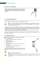
There are two antenna sockets: for 3G and WLAN communication.
After plugging the antenna into the socket, the screw should be tightened to light resistance only. Do not
over tighten this connector.
3.2 C
ONTROL PANEL
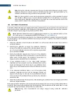
SV 200A is dedicated for the outdoor monitoring and remote control via mobile 3G network, LAN or WLAN.
However, it can be also controlled from the control panel with the use of five keys and a display (128 x 32
pixel resolution).
During outdoor operation, the control panel should
be closed by the flap. Closed flap assures protection
of the
instrument’s user interface from environmental
impact and, what is more important, assures that
acoustical direction characteristics are within
declared tolerances.
Содержание SV 200A
Страница 123: ...123 SV 200A User Manual Appendix A REMOTE CONTROL firmware revision 1 x x Under development ...
Страница 153: ...153 SV 200A User Manual Free Field Frequency response of SV 200A ...
Страница 164: ...164 SV 200A User Manual 250 Hz 315 Hz 90 deg 0 deg 90 deg 0 deg 400 Hz 500 Hz 90 deg 0 deg 90 deg 0 deg ...
Страница 165: ...165 SV 200A User Manual 630 Hz 800 Hz 90 deg 0 deg 90 deg 0 deg 1000 Hz 1250 Hz 90 deg 0 deg 90 deg 0 deg ...
Страница 166: ...166 SV 200A User Manual 1600 Hz 2000 Hz 90 deg 0 deg 90 deg 0 deg 2240 Hz 2500 Hz 90 deg 0 deg 90 deg 0 deg ...
Страница 167: ...167 SV 200A User Manual 2800 Hz 3150 Hz 90 deg 0 deg 90 deg 0 deg 3550 Hz 4000 Hz 90 deg 0 deg 90 deg 0 deg ...
Страница 168: ...168 SV 200A User Manual 4500 Hz 5000 Hz 90 deg 0 deg 90 deg 0 deg 5600 Hz 6300 Hz 90 deg 0 deg 90 deg 0 deg ...
Страница 169: ...169 SV 200A User Manual 7100 Hz 8000 Hz 90 deg 0 deg 90 deg 0 deg 8500 Hz 9000 Hz 90 deg 0 deg 90 deg 0 deg ...
Страница 170: ...170 SV 200A User Manual 9500 Hz 10000 Hz 90 deg 0 deg 90 deg 0 deg 10600 Hz 11200 Hz 90 deg 0 deg 90 deg 0 deg ...
Страница 177: ...177 SV 200A User Manual 8 0 kHz 1 1 octave filter 4 0 kHz 1 1 octave filter 2 0 kHz 1 1 octave filter ...
Страница 178: ...178 SV 200A User Manual 1 0 kHz 1 1 octave filter 500 Hz 1 1 octave filter 250 Hz 1 1 octave filter ...
Страница 179: ...179 SV 200A User Manual 125 Hz 1 1 octave filter 63 0 Hz 1 1 octave filter 31 5 Hz 1 1 octave filter ...


