Set-up
Technical Handbook
019722-101 Rev. 05
31
SC-350/360
7.10 8 - Adjustment of Sensitivity
of Hopper (SC 360)
This function sets the time delay between the stop of the flow of
coins and the restart of the hopper.
Press
Q
until the number “8” is shown at the far left of the display.
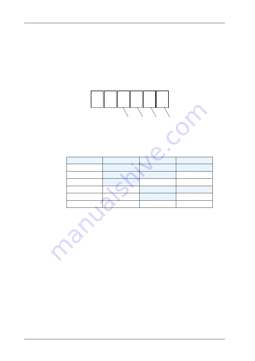
The display also shows four other numbers which are detailed below:
Example (default setting):
(a), (b) and (c) Time delay settings
The time delay is set by (a), (b) and (c) and varies between 0 and
1990 ms.
d) Not used (=0)
7.11 Accessing Statistics Registers
To get information about the use of the machine, use the following
functions:
a) Press and hold
Q
and
ACC
at the same time, while switching the
machine
On
.
b) When the display changes from showing a row of “8”s to
“S t A t”, release
Q
and
ACC
.
The machine is now in the
statistics
mode.
Total number of times the motor has started and reversed:
Hold down
M
. The display shows “S t A r t” and then the
number of times that the motor has started and reversed since
the last time the value was reset.
>>>
Time delay (ms)
a
b
c
0
0 (default)
0 (default)
0 (default)
10-90
0
0
1-9
100-990
0
1-9
0-9
1000
1
0
0
1010-1090
1
0
1-9
1100-1990
1
1-9
0-9
8
0
0
0
0
a (0-1) b (0-9) c (0-9) d (0-1)
Содержание ARPEGE SECURITY SC-350
Страница 1: ......
Страница 2: ......
Страница 3: ......
Страница 105: ...Interconnection Diagram Technical Handbook 019722 101 Rev 05 95 SC 350 360 13 3 CPU Board Circuit Diagram CPU...
Страница 107: ...Interconnection Diagram Technical Handbook 019722 101 Rev 05 97 SC 350 360 13 5 CPU Board Layout 0 0 0 0 1 0 0 2 3...
Страница 108: ...Interconnection Diagram Technical Handbook 019722 101 Rev 05 98 SC 350 360 13 6 PSU Board Circuit Diagram...
Страница 109: ...Interconnection Diagram Technical Handbook 019722 101 Rev 05 99 SC 350 360 13 7 PSU Board Layout...
Страница 111: ...Interconnection Diagram Technical Handbook 019722 101 Rev 05 101 SC 350 360 13 9 Serial Interface Board Layout...
Страница 112: ...Interconnection Diagram Technical Handbook 019722 101 Rev 05 102 SC 350 360 13 10 RD AUX Interface Circuit Diagram...
Страница 113: ...Interconnection Diagram Technical Handbook 019722 101 Rev 05 103 SC 350 360 13 11 RD AUX Interface Board Layout...
Страница 114: ......


