Control and Display Elements
3-2
3.1.2
Status LEDs
The following status LEDs are at the operating device:
3.2
Touch Screen
The device is equipped with a resistive 4 wire touch screen. You operate the device
using this touch screen.
3.3
User Mode Switch
The user mode switch is located on the rear of the operating device.
Legend for table:
I = Switch ON
– = Switch OFF
X = Any switch position
Help
Indicates an upcoming system message
Edit
Indicates the editing mode
Pointed or sharp objects, such as pens or fingernails, can lead to irreparable dam-
ages of the touch screen. Exclusively therefore use the fingertips or the aids indi-
cated in the technical data for the operation.
To protect the touch screen you can use special protection foils. You receive corre-
sponding protection foils directly from Sütron electronic.
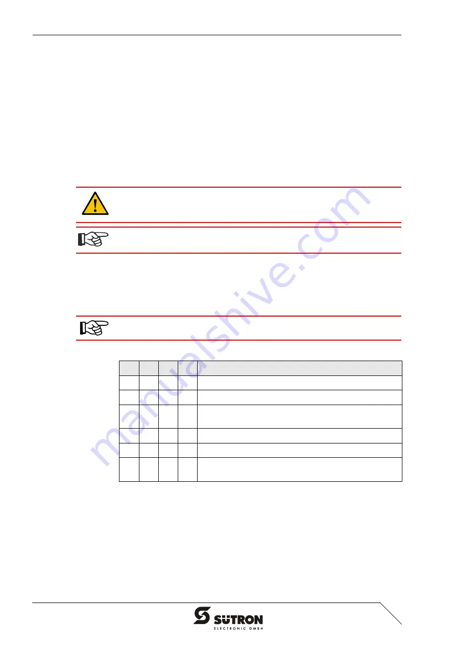
The switch positions for ON or OFF are printed onto the user mode switch.
Table 3-1
User mode switch
S1
S2
S3
S4
Operating Mode
I
X
–
–
Standard Mode with PLC (Default Upon Delivery)
I
X
I
–
Standard Mode without PLC
I
–
–
I
Activate Download (Erases the Application Memory) and
Default Contrast / Brightness Setting
I
–
I
I
Activate Upload
–
–
–
–
Calibration Mask is Called-up on Start-up
–
–
I
–
Calibration Mask is Called-up on Start-up and the Calibra-
tion Process is Started Immediately
Содержание TesiMod TP22
Страница 5: ...iii Overall Table of Contents 7 Ordering Data 7 1 A Index A 1...
Страница 6: ...Overall Table of Contents 1 iv...
Страница 10: ...Installation and Commissioning 2 2 2 2 1 Front Panel Dimensions Figure 2 1 Front panel dimensions...
Страница 48: ...Interfaces of the Device 4 28...
Страница 52: ...Maintenance and Servicing 5 4...
Страница 58: ...Ordering Data 7 2...
Страница 61: ......


