Vibroacoustic noise systems
SEL SP-55
Operation
manual
Страница 1: ...Vibroacoustic noise systems SEL SP 55 Operation manual ...
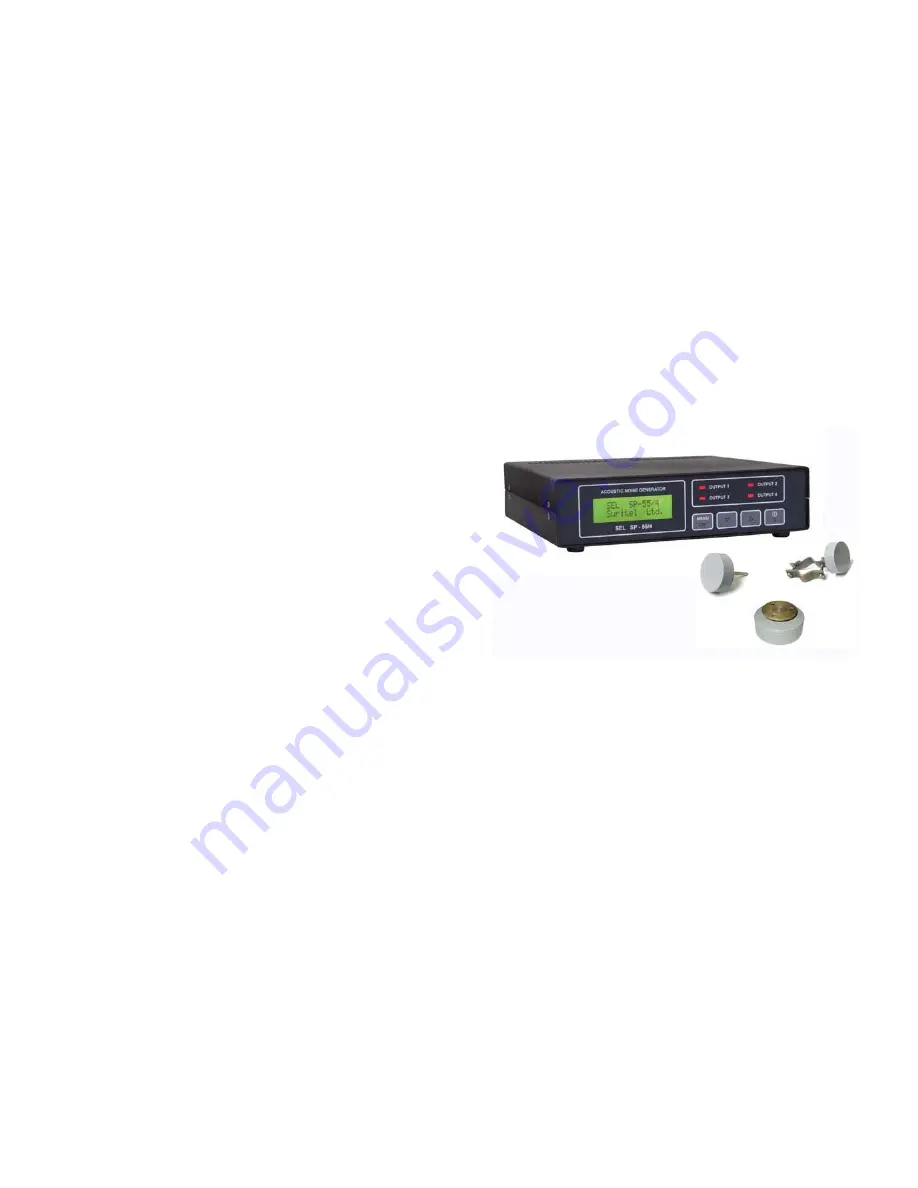
Страница 2: ... information leakage in rooms by vibroacoustic channel with built in equalizer using which you can set the noise level the integrated output power suitable for your conditions and its spectrum in octave strips on each channel The system might contain digital vibroacoustic noise generator SEL SP 55 2 2 channels SEL SP 55 4 4 channels electromagnetic vibro transducers SEL SP 55 V universal SEL SP 55...
Страница 3: ...ystem settings mode The default settings 1 Noise is disabled in all channels 2 Management of the system turning on off the noise generation ON from the front panel OFF from the RC 1 1 Functional characteristics The system provides Active protection by wide range acoustic and vibroacoustic noise for the informational objects from microwave systems including laser microphones used for interception o...
Страница 4: ...p to 100 atmospheric pressure 750 40 mm Hg Appendix No 1 Recommendations to installing SEL SP 55 systems I Placing electromagnetic vibro transducers and acoustic radia tors Recommendations Vibro transducers SEL SP 55 V should be installed in regular intervals in chessboard order not more than 3 m from each other and not closer than 1 m from corners of sides of protected volumes connection of the n...
Страница 5: ... not required II Package contents Name Quantity 1 The system set 1 1 SEL SP 55 2 generator ___ pcs 1 2 SEL SP 55 4 generator ___ pcs 1 3 SEL SP 51 V electromagnetic vibro transducer ___ pcs 1 4 SEL SP 51 VG electromagnetic vibro transducer ___ pcs 1 5 Acoustic speaker 8 Ohm ___ pcs 2 The operating manual ___ pcs 3 The optional equipment 3 1 Acoustic start microphone ___ pcs 3 2 RC set ___ pcs 3 3 ...
Страница 6: ...y to the producer Please note that the warranty does not apply if the system or its parts have been unsealed or dismantled 5 1 5 Preservation Conservation includes the following operations one after another maintenance works drying during 4 hours at room temperature packing into any rigid container that exclude damage of the system placing the generator to a warmed depository at 5 С 35 С up to 80 ...
Страница 7: ... be used until the emergency situation will be solved V Maintenance works and repair 5 1 Maintenance works 5 1 1 General instructions Maintenance works are conducted in order to provide proper operation of the system Maintenance works include visual external examination and cleaning of the system and its components You should prevent accumulation of dust on the front panel Use a soft cloth to dust...
Страница 8: ...C button II Push buttons to choose the number of the channel to setup the 1 st channel is chosen To return back to WORKING mode push C button ATTENTION Some errors with loading and generation of OUTPUT1 the noise for the channel channel No 1 Next action check up the loading of the channel changing the loading and level of noise signal for the channel ATTENTION Overloading short circuit of the chan...
Страница 9: ...mber of channel Next action turn ON generation of noise using RC or setup managing of the generator from the front panel GOOD The loading and generation of the noise in norm OUTPUT1 for the first channel channel No 1 III Push MENU OK button to confirm the choused channel and enter to its setup menu To return back to WORKING mode push C button IV Enter to level setup menu by pushing MENU OK button ...
Страница 10: ...ement or wire RC is disabled acoustic start is disabled To turn ON the corresponding type use buttons and confirm it with MENU OK button or wire RC is enabled wire RC is disabled OR or acoustic start is enabled acoustic start is disabled NOTE In setup of acoustic start mode the current sound level and the start level is displayed Use buttons to set needed start level If the start level is at minim...