MCPD18 R104
1-channel MCP Detector
MCPD18
(Release 104)
Manual
1
Страница 1: ...MCPD18 R104 1 channel MCP Detector MCPD18 Release 104 Manual 1...
Страница 2: ...r permission of Surface Concept GmbH Surface Concept GmbH Am S gewerk 23a 55124 Mainz Germany Tel 49 6131 627160 Fax 49 6131 6271629 www surface concept com support surface concept de User manual for...
Страница 3: ...Operation of the MCPD18 8 4 1 Getting Started 8 4 1 1 Start Up Procedure 8 4 1 2 Dark Count Rate Measurement 9 4 1 3 Standard Detector Measurement 9 4 2 Standard Operation Procedure 10 4 3 Bake Out P...
Страница 4: ...the microchannel plates and the MCP detector 2 2 Safety Instructions Please read this manual carefully before performing any electrical or electronic operations Strictly follow the safety rules given...
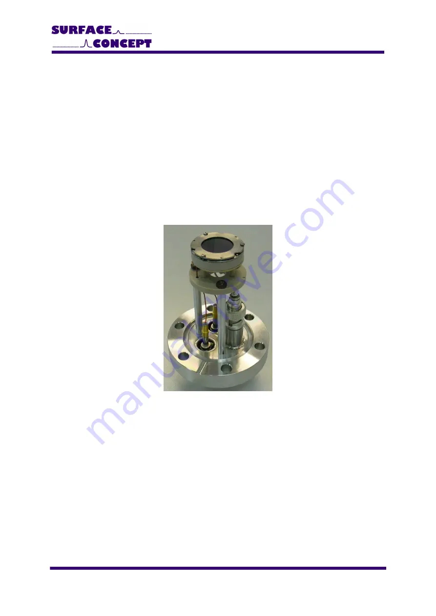
Страница 5: ...l MCP detector It consist of a chevron microchannel plate stack and a detector anode MCP pulses are capacitively coupled into the anode The anode is a 50Ohm matched system and signal readout is realiz...
Страница 6: ...ceed as follows to install it into your vacuum chamber Vent the package carefully Unpack the detector carefully Before installing the detector to your chamber check the front side of the MCP stack for...
Страница 7: ...F for the high voltage supply and one BNC connector labeled SIG for the signal output MCP B connects the high voltage part of the detector anode and the back side of the MCP stack while MCP F connects...
Страница 8: ...Ps very fast Turn off ion pumps and ion gauges before turning on the high voltage of the detector Turn on the high voltage carefully The voltage increase should not exceed 400V per minute A schematic...
Страница 9: ...lary 1600V 4 1 2 Dark Count Rate Measurement Check the detector output by means of any electronics and software or with an oscilloscope where the input is terminated with 50Ohms The dark count rate wi...
Страница 10: ...Observe the chamber pressure carefully every time the high voltage is turned on Switch off the high voltage immediately in case of a temporary pressure rise by an order of magnitude or more This indic...
Страница 11: ...MCPD18 R104 Do not remove the blankets until the entire system has thoroughly cooled off Do not operate the detector before the temperature has returned to ambient conditions 11...
Страница 12: ...l while the signal readout is realized close to ground potential in respect to the high voltage of the MCPs A pulse coupling layer is used to isolate the high voltage from the ground potential within...
Страница 13: ...for the R104 The resistance between MCP F and MPC B resistance of MCP stack and internal resistor should be in the range of 100 400 M the exact values are given in the specification sheet of the detec...
Страница 14: ...dling MCPs No physical object should come into contact with the active area of the wafer The MCP should be handled by its rims there is no solid glass border Use clean degassed tools fabricated from s...
Страница 15: ...e maximum voltage given in P and in the specification sheet of the detector Higher potentials may result in irreversible damage MCPs can be degraded by exposure to various types of hydrocarbon materia...
Страница 16: ...est count rates during the test phase Therefore gain degradation will be still significant in the first year of operation or even longer depending on applied count rates and becomes obvious by a decli...
Страница 17: ...oltage Do as follows to measure an MCP curve Start the detector operation with a homogeneous illumination as good as possible Use an appropriate device to measure the count rate output of the detector...
Страница 18: ...erated at a high count rate of several Mcps for a time period of about 8 hours It is really important that the detector is irradiated homogeneously over the complete active area Otherwise the MCPs wil...
Страница 19: ...t detector see specification sheet Voltage at MCP front see specification sheet HV connections 2 SHV connectors MCP front MCP back Connections for signal 1 BNC connector 50Ohm matched coaxial signal M...
Страница 20: ...tor elements 12 Figure 4 Internal connection of the high voltage potentials schematic for the R104 13 Figure 5 Typical gain degradation of MCPs as function of the extracted output charge 16 Figure 6 S...