


23
Chapter 1: Introduction
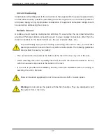
Figure 1-15. RSC-X11OPi-PCIE Card on the Reverse Side of the 7089P-TR4T Midplane
(w/5 PCI-E Cards max.)
BPN-X11OPi
Midplane
(Reverse Side)
Five (5)
RSC-X11OPi-PCIE
on the Rear side of
Midplane
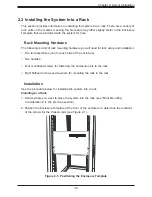
Figure 1-16. RSC-X11OPi-PCIE Card Layout (Front)
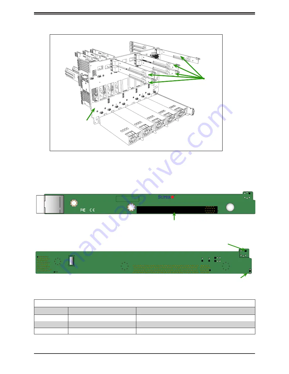
Figure 1-17. RSC-X11OPi-PCIE Card Layout (Reverse Side)
D1
SW1
Hot-Plug Attention SW (SW1)
Hot-Plug Attention LED (D1)
Major Components on the RSC-X11OPi-PCIE Card
BAR CODE
RSC-X11OPi-PCIE
Rev. 1.00
J1
J2
SLOT1 PCI-E 3.0 X16
Slot1 PCI-E 3.0x16 (J2)
Major Components on the RSC-X11OPi-PCIE
Location
Description
Detailed
Description
Front Side
J2
PCI-E Slot1: PCI-E 3.0 x16 slot
Reverse Side
SW1
Hot-plug attention button
Reverse Side
D1
Hot-plug attention LED (Orange: Hot-plug support needs attention)
Содержание SuperServer 7089P-TR4T
Страница 1: ...USER S MANUAL Revision 1 0 SuperServer 7089P TR4T ...
Страница 56: ...SuperServer 7089P TR4T User s Manual 56 Figure 3 4 Removing a PCI E Card from a PCIE Module 5 6 ...
Страница 59: ...59 Chapter 3 Maintenance and Component Installation Figure 3 6 Installing a PCI E Card in a CPU Module ...
Страница 60: ...SuperServer 7089P TR4T User s Manual 60 Figure 3 7 Installing a PCI E Card in a CPU Module cont ...
Страница 62: ...SuperServer 7089P TR4T User s Manual 62 Figure 3 9 Installing a PCI E Card in a Storage Module ...
Страница 64: ...SuperServer 7089P TR4T User s Manual 64 Figure 3 11 Installing the Battery 3 2 ...
Страница 69: ...69 Chapter 3 Maintenance and Component Installation Figure 3 16 Installing Removing 2 5 HDDs with bracket ...