


49
48
Chapter 4: Motherboard Connections
SuperServer 5019S-M/MR User's Manual
4.3 Ports
Serial Ports
Two COM ports (COM1 & COM2) are located on the motherboard. COM1 is a port located
on the I/O back panel. COM2 is a header located next to COM1.
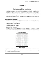
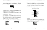
Rear I/O Ports
See the figure below for the locations and descriptions of the various I/O ports on the rear
of the motherboard.
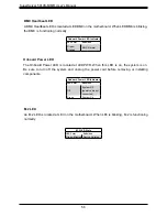
SATA Ports
The X11SSH-F includes a total of eight SATA ports, supported by the Intel C236 PCH chip.
These SATA ports support RAID 0, 1, 5, and 10.
Notes
: I-SATA0 and I-SATA1 are Supermicro SuperDOMs. These are yellow SATADOM ports
with power pins built in and do not require separate external power cables. These ports are
backward-compatible with non-Supermicro SATADOMs that do require external power.
For more information on the SATA HostRAID configuration, please refer to the Intel SATA
HostRAID user's guide posted on our website at
Figure 4-2. Rear I/O Ports
Rear I/O Ports
#
Description
#
Description
1.
COM1 Port
6
USB6 (3.0)
2.
IPMI LAN Port
7
LAN1 Port
3
USB1 (2.0)
8
LAN2 Port
4
USB0 (2.0)
9
VGA Port
5
USB7 (3.0)
10 UID Switch
1
9
8
7
6
5
4
3
2
10
Data Cables
The data cables in the system have been carefully routed to maintain airflow efficiency. If
you disconnect any of these cables, take care to re-route them as they were originally when
reconnecting them.
Important!
Make sure the the cables do not come into contact with the fans.
Power Cables
Three power connections on the X11SSH-F must be connected to the power supply. The
wiring is included with the power supply.
•
24-pin Primary ATX Power (JPWR1)
•
8-pin Processor Power (JPWR2)
NMI Button
The non-maskable interrupt button header is located on pins 19 and 20 of JF1.
NMI Button
Pin Definitions (JF1)
Pin#
Definition
19
Control
20
Ground


