background image

2-4

2-5

Chapter 2: Warning Statements for AC Systems

SC721 Chassis Manual

Installation Instructions

 Warning!

Read the installation instructions before connecting the system to the power source.

Warnung

Vor dem Anschließen des Systems an die Stromquelle die Installationsanweisungen 

lesen.

¡Advertencia! 
Lea las instrucciones de instalación antes de conectar el sistema a la red de 
alimentación.

Attention 
Avant de brancher le système sur la source d'alimentation, consulter les directives 
d'installation.

Circuit Breaker

 Warning!

This product relies on the building's installation for short-circuit (overcurrent) 

protection. Ensure that the protective device is rated not greater than: 250 V, 20 A.

設置手順書

システムを電源に接続する前に、設置手順書をお読み下さい。

시스템을 전원에 연결하기 전에 설치 안내를 읽어주십시오.

Waarschuwing 
Raadpleeg de installatie-instructies voordat u het systeem op de voedingsbron 
aansluit.

サーキット・ブレーカー

この製品は、短絡(過電流)保護装置がある建物での設置を前提としています。

保護装置の定格が250 V、20 Aを超えないことを確認下さい。

Warnung 

Dieses  Produkt  ist  darauf  angewiesen,  dass  im  Gebäude  ein  Kurzschluss- 

bzw. Überstromschutz installiert ist. Stellen Sie sicher, dass der Nennwert der 

Schutzvorrichtung nicht mehr als: 250 V, 20 A beträgt.

¡Advertencia! 
Este equipo utiliza el sistema de protección contra cortocircuitos (o sobrecorrientes) 

del edificio. Asegúrese de que el dispositivo de protección no sea superior a: 250 
V, 20 A.

Attention 
Pour ce qui est de la protection contre les courts-circuits (surtension), ce produit 

dépend  de  l'installation  électrique  du  local.  Vérifiez  que  le  courant  nominal  du 
dispositif de protection n'est pas supérieur à :250 V, 20 A.

警告

将此系统连接电源前,请先阅读安装说明。

警告

將系統與電源連接前,請先閱讀安裝說明。

警告

此产品的短路(过载电流)保护由建筑物的供电系统提供,确保短路保护设备的额定电

流不大于250V,20A。

警告

此產品的短路(過載電流)保護由建築物的供電系統提供,確保短路保護設備的額定電

流不大於250V,20A。

Содержание PWS-251-1H

Страница 1: ...SC721 CHASSIS SERIES SC721TQ 250B USER S MANUAL 1 0a ...

Страница 2: ...roduction of this product is not allowed except as expressly permitted by the terms of said license IN NO EVENT WILL SUPERMICRO BE LIABLE FOR DIRECT INDIRECT SPECIAL INCIDENTAL SPECULATIVE OR CONSEQUENTIAL DAMAGES ARISING FROM THE USE OR INABILITY TO USE THIS PRODUCT OR DOCUMENTATION EVEN IF ADVISED OF THE POSSIBILITY OF SUCH DAMAGES IN PARTICULAR SUPERMICRO SHALL NOT HAVE LIABILITY FOR ANY HARDWA...

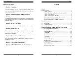
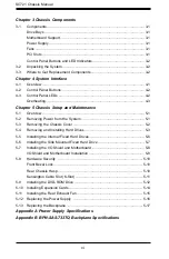
Страница 3: ...ven in this chapter when installing removing or reconfiguring your chassis Appendix A Power Supply Specifications Appendix B BPN SAS 733TQ Backplane Specifications Contents Preface Manual Organization iv Chapter 1 Introduction iv Chapter 2 Standardized Warning Statements for AC Systems iv Chapter 3 System Interface iv Chapter 4 Chassis Setup and Maintenance iv Appendix A Chassis Cables Screws and ...

Страница 4: ...e System 5 1 5 3 Removing the Chassis Cover 5 2 5 4 Removing and Installing Hard Drives 5 3 5 5 Installing the Internal Fixed Hard Drives 5 6 5 6 Installing the Side Mounted Fixed Hard Drive 5 7 5 7 Installing the I O Shield and Motherboard 5 8 I O Shield and Motherboard Installation 5 8 5 8 Hardware Security 5 10 Front Bezel Lock 5 10 Rear Chassis Hasp 5 10 Kensington Cable Slot K Slot 5 11 5 9 I...

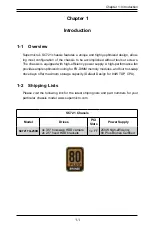
Страница 5: ...ample optimized cooling for FB DIMM memory modules and four hot swap drive bays offer maximum storage capacity Default Design for 84W TDP CPU 1 2 Shipping Lists Please visit the following link for the latest shiping lists and part numbers for your particular chassis model www supermicro com Chapter 1 Introduction 1 1 SC721 Chassis Model Drives PCI Slots Power Supply SC721TQ 250B 4x 3 5 hot swap HD...

Страница 6: ...at it does not shift within the carton and become damaged during shipping This warranty only covers normal consumer use and does not cover damages in curred in shipping or from failure due to the alteration misuse abuse or improper maintenance of products During the warranty period contact your distributor first for any product problems 1 3 Contacting Supermicro Headquarters Address Super Micro Co...

Страница 7: ...SC721 Chassis Manual 1 4 Notes ...

Страница 8: ... configuring components in the Supermicro chassis These warnings may also be found on our web site at http www supermicro com about policies safety_information cfm Warning This warning symbol means danger You are in a situation that could cause bodily injury Before you work on any equipment be aware of the hazards involved with electrical circuitry and be familiar with standard practices for preve...

Страница 9: ...ÉCURITÉ Ce symbole d avertissement indique un danger Vous vous trouvez dans une situation pouvant entraîner des blessures ou des dommages corporels Avant de travailler sur un équipement soyez conscient des dangers liés aux circuits électriques et familiarisez vous avec les procédures couramment utilisées pour éviter les accidents Pour prendre connaissance des traductions des avertissements figuran...

Страница 10: ...rschuwing Raadpleeg de installatie instructies voordat u het systeem op de voedingsbron aansluit サーキッ ト ブレーカー この製品は 短絡 過電流 保護装置がある建物での設置を前提としています 保護装置の定格が250 V 20 Aを超えないこ とを確認下さい Warnung Dieses Produkt ist darauf angewiesen dass im Gebäude ein Kurzschluss bzw Überstromschutz installiert ist Stellen Sie sicher dass der Nennwert der Schutzvorrichtung nicht mehr als 250 V 20 A beträgt Advertencia Est...

Страница 11: ...페어 를 초과하지 않도록 해야 합니다 Waarschuwing Dit product is afhankelijk van de kortsluitbeveiliging overspanning van uw electrische installatie Controleer of het beveiligde aparaat niet groter gedimensioneerd is dan 220V 20A Advertencia El sistema debe ser disconnected de todas las fuentes de energía y del cable eléctrico quitado de los módulos de fuente de alimentación antes de tener acceso el interior del ...

Страница 12: ...tenance de ces équipements à des personnels qualifiés et expérimentés 경고 훈련을 받고 공인된 기술자만이 이 장비의 설치 교체 또는 서비스를 수행할 수 있습니다 Waarschuwing Deze apparatuur mag alleen worden geïnstalleerd vervangen of hersteld door geschoold en gekwalificeerd personeel Warnung Diese Einheit ist zur Installation in Bereichen mit beschränktem Zutritt vorgesehen Der Zutritt zu derartigen Bereichen ist nur mit einem Spezial...

Страница 13: ...r la batería exclusivamente con el mismo tipo o el equivalente recomendado por el fabricante Desechar las baterías gastadas según las instrucciones del fabricante 경고 이 장치는 접근이 제한된 구역에 설치하도록 되어있습니다 특수도구 잠금 장치 및 키 또는 기타 보안 수단을 통해서만 접근 제한 구역에 들어갈 수 있습니다 Waarschuwing Dit apparaat is bedoeld voor installatie in gebieden met een beperkte toegang Toegang tot dergelijke gebieden kunnen alleen verkregen wo...

Страница 14: ...ückwandplatine gefährliche Spannungen oder Energien auf Vorsicht bei der Wartung Advertencia Cuando el sistema está en funcionamiento el voltaje del plano trasero es peligroso Tenga cuidado cuando lo revise Attention Lorsque le système est en fonctionnement des tensions électriques circulent sur le fond de panier Prendre des précautions lors de la maintenance Warning Hazardous voltage or energy is...

Страница 15: ...이나 에너지가 발생 합니다 서비스 작업 시 주의하십시오 Waarschuwing Een gevaarlijke spanning of energie is aanwezig op de backplane wanneer het systeem in gebruik is Voorzichtigheid is geboden tijdens het onderhoud Attention L équipement doit être installé conformément aux normes électriques nationales et locales 경고 현 지역 및 국가의 전기 규정에 따라 장비를 설치해야 합니다 Waarschuwing Bij installatie van de apparatuur moet worden voldaan aan d...

Страница 16: ...teur 경고 움직이는 위험한 부품 회전하는 송풍 날개에 접근하지 마세요 섀시로부터 팬 조립품을 제거할 때 팬은 여전히 회전하고 있을 수 있습니다 팬 조림품 외관의 열려있는 부분들로부터 손가락 및 스크류드라이버 다른 물체들이 가까이 하지 않도록 배치해 주십시오 Waarschuwing Gevaarlijk bewegende onderdelen Houd voldoende afstand tot de bewegende ventilatorbladen Het is mogelijk dat de ventilator nog draait tijdens het verwijderen van het ventilatorsamenstel uit het chassis Houd uw vingers schroevendraaiers en ev...

Страница 17: ...ezeigt haben Advertencia Al instalar el producto utilice los cables de conexión previstos o designados los cables y adaptadores de CA La utilización de otros cables y adaptadores podría ocasionar un mal funcionamiento o un incendio Aparatos Eléctricos y la Ley de Seguridad del Material prohíbe el uso de UL o CSA cables certificados que tienen UL o CSA se muestra en el código de otros dispositivos ...

Страница 18: ...2 20 SC721 Chassis Manual Notes ...

Страница 19: ...pports the drives below Four hot swappable 3 5 hard drives Two internal fixed 2 5 hard drives Motherboard Support Supports a wide range of Mini ITX motherboards from ATOM to Core i7 Power Supply Each chassis includes a high efficiency power supply The 250W unit has an 80 Bronze level certification Fans The chassis includes a 12cm rear fan with 25db whisper quiet operation PCI Slots The chassis inc...

Страница 20: ...Unpacking the System Inspect the box in which the chassis was shipped and note if it was damaged If the chassis itself shows damage file a damage claim with the carrier 3 3 Where to Get Replacement Components Infrequently you may need replacement parts for your system To ensure the highest level of professional service and technical support we recommend purchasing ex clusively from our Supermicro ...

Страница 21: ...l panel which is located on the front of the chassis behind the front bezel This panel features power buttons and status moni toring lights These elements are described in this chapter with possible responses that you may need to take Figure 4 1 Front Chassis Panels Power Button Reset Button USB Ports LEDs ...

Страница 22: ...low Overheating There are several possible responses if the system overheats If the system overheats 1 Use the LEDs to determine the nature of the overheating condition 2 Confirm that the chassis cover is installed properly 3 Check the routing of the cables and make sure all fans are present and operat ing normally 4 Verify that the heatsinks are installed properly Informational LED Status Descrip...

Страница 23: ...SC721 Chassis Manual 4 4 Notes ...

Страница 24: ...lips screwdriver 5 2 Removing Power from the System Before performing setup or maintenance tasks use the following procedure to ensure that power has been removed from the system 1 Use the operating system to power down the system following the on screen prompts 2 After the system has completely shut down carefully grasp the head of the power cord and gently pull it out of the back of the power su...

Страница 25: ...ort periods of time do not operate the server without the cover in place The chassis cover must be in place to allow proper airflow and prevent overheating Figure 5 1 Removing the Chassis Cover 1 4 1 4 1 2 3 5 4 Removing and Installing Hard Drives The SC721 chassis supports four 3 5 hot swappable hard drives in hard drive carriers These hard drives can be removed from the chassis without powering ...

Страница 26: ... until the drive carrier clicks into the locked position 4 Close and lock the front bezel Installing a Hard Drive into the Hard Drive Carrier 1 Remove the six screws which secure the dummy drive into the hard drive carrier 2 Remove the dummy drive from the hard drive carrier 3 Install a new hard drive into the hard drive carrier with the printed circuit board side facing down so that the mounting ...

Страница 27: ...as illustrated above and secure it to the chassis with two screws 4 Replace the chassis cover plug the power cord into the rear of the power supply and power up the system 5 6 Installing the Side Mounted Fixed Hard Drive Figure 5 6 Installing the Side Mounted Fixed Hard Drive Installing the Side Mounted Fixed Hard Drive 1 Power down the system and plug the power cord into the rear of the power sup...

Страница 28: ...ower supply as described in Section 5 2 then remove the chassis cover as described in Section 5 3 3 Remove the three screws securing the rear tray to the rear of the chassis and set them aside for later use 4 Pull the rear tray out from the chassis Figure 5 7 Removing the Rear Tray from the Chassis 1 4 Installing the Motherboard and I O Shield 1 With the illustrations facing the outside of the cha...

Страница 29: ...nd unlock the bezel Always remove the key from the lock and store the key in a secure place Rear Chassis Hasp Unauthorized entry through the rear of the chassis may be discouraged by placing a lock on the rear of the chassis The SC721 chassis is equipped with a rear chas sis hasp that can accomodate a variety of commonly available locks not included Kensington Cable Slot K Slot The SC721 chassis f...

Страница 30: ...securing the cover plate to the front of the chassis and set them aside for later use 4 Some SC721 chassis include a top hard drive bracket Remove this bracket if it is present by carefully grasping the bracket at the back of the DVD ROM bay and gently removing it from the back of the drive bay Lift it up and out of the chassis 5 Install the bracket rail A onto the lefthand side of the device and ...

Страница 31: ...place the chassis cover plug the power cord into the rear of te power sup ply and power up the system 5 10 Installing Expansion Cards The SC721 chassis includes one PCI slot for an expansion card 5 6 5 11 Installing the Rear Exhaust Fan The SC721 includes a 12 cm rear exhaust fan that provides cooling for the chassis The chassis features a set of mounting holes which will support a standard 9 cm e...

Страница 32: ...upply model 5 Secure the new power supply using the screws previously set aside 6 Replace the chassis cover plug the power cord into the rear of the power supply and power up the system Replacing the Backplane 1 Power down the system and remove the power cord from the rear of the power supply as described in Section 5 2 and remove the chassis cover as described in Section 5 3 2 Remove the screw se...

Страница 33: ...SC721 Chassis Manual 5 18 Notes ...

Страница 34: ...ly specifications for your chassis system The SC721 chassis includes a power supply rated at 80 Plus Bronze Level SC721TQ 250B 250W MFR Part PWS 251 1H AC Voltage 100 240V 50 60Hz 5 Amp 5V Max 14 Amp Min 0 5 Amp 12V Max 3 Amp Min 0 Amp 12V Max 3 Amp Min 0 Amp 3 3V Max 12 Amp Min 0 3Amp 5VSB Max 2 5 Amp Min 0 Amp ...

Страница 35: ...SC721 Chassis Manual A 2 Notes ...

Страница 36: ...t static discharge Touch a grounded metal object before removing a component from the antistatic bag Handle the backplane by its edges only do not touch its components peripheral chips memory modules or gold contacts When handling chips or modules avoid touching their pins Put the card and peripherals back into their antistatic bags when not in use B 2 General Safety Guidelines Always disconnect p...

Страница 37: ...igned to utilize the most up to date technology available providing your system with reliable high quality performance This manual reflects BPN SAS 733TQ Revision 1 02 the most current release avail able at the time of publication Always refer to the Supermicro website at www su permicro com for the latest updates compatible parts and supported configurations B 5 Front Connectors Front Connectors ...

Страница 38: ...ideband Headers Pin Definition Pin Definition 2 SDIN Backplane Addressing SB5 1 Controller ID SB6 4 SDOUT I2 C Reset SB4 3 GND SB2 6 GND SB3 5 SLOAD SDA SB1 8 Backplane ID SB7 7 SCLOCK SCL SB0 10 No Connec tion 9 No Connec tion 6 Fan Header The fan header is designated FAN JP22 7 MG9071 Chip The MG9071 is an enclosure management chip that supports the SES 2 controller and protocols 5 Activity LED ...

Страница 39: ...s can be used to choose between optional settings Jumpers create shorts between two pins to change the function of the connector Pin 1 is identified with a square solder pad on the printed circuit board Note On two pin jumpers Closed Connector Pins Jumper Setting 3 2 1 3 2 1 The buzzer sound indicates that a condition requiring immediate attention has occurred The buzzer alarm is triggered by the ...

Страница 40: ... SAS 1 J2 SAS SATA HDD 1 SAS 2 J3 SAS SATA HDD 2 SAS 3 J4 SAS SATA HDD 3 SAS 0 J1 J2 J3 J4 SAS 2 SAS 1 SAS 3 Figure B 5 Rear Connectors LED Indicators LED Status Description D3 On Overheated condition drive failure or fan failure D4 On Fan failure ACT IN LED Blinking HDD activity SUPER BPN SAS 733TQ ACT IN LED MAIN PWR MAIN PWR JP26 JP46 FAN JP22 JP61 R JP47 JP42 JP51 JP44 JP40 JP50 JP29 I2C JP33 ...

Страница 41: ...SC721 Chassis Manual Rear LED Indicators Rear Connector Hard Drive Activity Failure LED SAS 0 D12 D5 SAS 1 D13 D6 SAS 2 D14 D7 SAS 3 D15 D8 D5 D6 D7 D15 D14 D13 D12 D8 Figure B 6 Rear LED Indicators Rear LED Indicators SAS 0 J1 J2 J3 J4 SAS 2 SAS 1 SAS 3 Notes ...

Страница 42: ... reasonably expected to result in significant injury or loss of life or catastrophic property damage Accordingly Supermicro disclaims any and all liability and should buyer use or sell such products for use in such ultra hazardous applications it does so entirely at its own risk Furthermore buyer agrees to fully indemnify defend and hold Supermicro harmless for and against any and all claims deman...

Отзывы: