Supermicro A+ AS -2114GT-DNR Скачать руководство пользователя страница 16

16

A+ Server AS -2114GT-DNR User's Manual
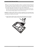
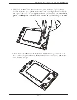
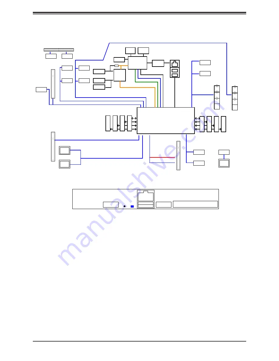
Note:

 This is a general block diagram and may not exactly represent the features on your 

motherboard. See the previous pages for the actual specifications of your motherboard.

Figure 1-6. Chipset Block Diagram

5

5

4

4

3

3

2

2

1

1

D

D

C

C

B

B

A

A

H12SSG-AN6   AMD SP3 Rome Rev. 1.00

Rear I/O

01 Block Diagram-------  SSW-NTL
02 SMBus Diagram-------  SSW-NTL
03 Power Rail Diagram--  SSW-NTL
04 Clock Tree Diagram--  SSW-NTL
05 Reset Diagram-------  SSW-NTL
06 P0-MEM_CH_A_B-------  SSW-NTL
07 P0-MEM_CH_C_D-------  SSW-NTL
08 P0-MEM_CH_E_F-------  SSW-NTL
09 P0-MEM_CH_G_H-------  SSW-NTL
10 P0-DIMM-CH-A--------  SSW-NTL
11 P0-DIMM-CH-B--------  SSW-NTL   
12 P0-DIMM-CH-C--------  SSW-NTL
13 P0-DIMM-CH-D--------  SSW-NTL
14 P0-DIMM-CH-E--------  SSW-NTL
15 P0-DIMM-CH-F--------  SSW-NTL
16 P0-DIMM-CH-G--------  SSW-NTL
17 P0-DIMM-CH-H--------  SSW-NTL
18 P0-PCIe & SATA & GOP --------  SSW-NTL + AN6
19 P0-PCIe & SATA       --------  SSW-NTL + AN6
20 P0-USB & LPC & UART  --------  SSW-NTL + AN6
21 P0-CLK/RESET/SPI/SMB --------  SSW-NTL + AN6
22 P0-SVID/WAFL/JTAG    --------  SSW-NTL + AN6
23 P0-POWER-----------  SSW-NTL + AN6
24 P0-GROUND----------  SSW-NTL
25 P0 BYPASS CAP
26 P0-DIMM-BYPASS-CAP
27 P0-HW-STRAPs-----------------  SSW-NTL + AN6
28 P0-CLOCK BUFF-------X12DDW
29 Blank (SATA)
30 Blank (USB)
31 USB Rear I/O ------  SSW-NTL
32 PCI-E CPU0 P0&P1_LUIO
33 Blank (PCIe)
34 PCI-E CPU0 P2_OCP
35 PCI-E CPU0 P3_SlimSAS
36 PCI-E CPU0 G0&G1_RUIO
37 Blank (PCIe)
38 PCI-E CPU0 G2A&G2B_Impel
39 PCI-E CPU0 G2C&G2D_M2A/M2B
40 PCI-E CPU0 G3_RUIO
41 FAN & RT1 & RT2 ------  SSW-NTL
42 Front Panlel          ------  SSW-NTL
43 HDT                   ------  SSW-NTL +AN6
44 CPLD                  ------  AN6 + H12DGO
45 PCIe Reset            
46 SMBus                 ------  SSW-NTL + AN6
47 BMC TPM/INTRUDER/VGA  ------  SSW-NTL + AN6
48 BMC AST2600 DDR4/ESPI/SMB   ----- to AN6 p.48
49 BMC AST2600 SPI/UART/MAC    ----- to AN6 p.49
50 BMC AST2600 VGA/FAN/ADC/USB ----- to AN6 p.50
51 BMC AST2600 POWER/GND       ----- to AN6 p.51
52 BMC- BMC EXRST/RSMRST       ----- to AN6 p.52
53 Blank (NCSI)                ----- to AN6 p.53
54 BMC VOLTAGE RAGULATOR       ----- to AN6 p.54
55 BMC LAN RTL8211F-CG         ----- to AN6 p.55
56 BMC- COM & ROM  & SD        ----- to AN6 p.56
57 Blank

58 P0_VDDCR_CPU_RUN VRM        ----- to SST-PS p.58       
59 P0_VDDCR_CPU_RUN Phase 1-3  ----- to SST-PS p.59
60 P0_VDDCR_CPU_RUN Phase 5-7  ----- to SST-PS p.60
61 P0_VDDCR_SOC_RUN VRM        ----- to SST-PS p.61
62 P0_VDDCR_SOC_RUN Stage      ----- to SST-PS p.62
63 P0 ABCD VDDIO_VPP VRM       ----- to SST-PS p.63
64 P0 ABCD VDDIO Stage         ----- to SST-PS p.64
65 P0 ABCD VPP                 ------ X12DDW, p.71
66 P0 EFGH VDDIO VRM           ----- to SST-PS p.66
67 P0 EFGH VDDIO Stage         ----- to SST-PS p.67
68 P0 EFGH VPP                 ------ X12DDW, p.71
69 P0 VTT                      ------ to SSW-NTL p.68, 69.
70 P0 VDD1.8 RUN & DUAL        ------ to SSW-NTL p.70
71 P0 SOC DUAL                 ------ to SSW-NTL p.71
72 Blank
73 POWER CONNECTOR
74 HOT SWAP CONTROLLER  ------ from X12DGO-6, P.95
75 12V DUAL Control     ------ from H12DGO-6, P.107      
76 +VDD_5_DUAL          ------ from H12DGO-6, p.107
77 +VDD_33_DUAL         ------ from x12DDW-6, p.74
78 +VDD_5_RUN           ------ New
79 +VDD_33_RUN          ------- to H12DSG-CPU, p.110
80 OCP ISOLATION
81 OCP POWER
82 Manual Parts
83 History

USB1_HSD[2:3] 

+ USB1_SS[2:3]

USB_0_HSD[0,1]

CPU WAFL [1]

JMP3

SPI

CPU

BMC ROM

CPU G1 [15:0]

CPU P1 [15:0]

CPU G0 [15:0]

VGA

VGA

    BMC

AST2600

JSXB1

Impel

     x8

CPU P3 [15:0]

LPC

CPU G0 [15:8]

    PHY

RTL8211F

CPU G3 [15:8]

Dedicated

LAN

USB3.0 

EPYC Processor (AMD Socket SP3)

UID
LED

SPI

CPLD

M.2 Conn

M key

BIOS ROM

TPM

JAIOM1

DDR4

COM1

HEADER

CPU G3 PCIe[7:0] / SATA[37:30]

CPU P0 [15:0]

UID
BTN

Rear

  2X

 USB 3.0

IPMI LAN

   RJ45

A

J3

B

DD

R4

 D

IM

M

J4

J1

C

DD

R4

 D

IM

M

DD

R4

 D

IM

M

J2

D

DD

R4

 D

IM

M

J8

J5

F

DD

R4

 D

IM

M

J6

G

DD

R4

 D

IM

M

DD

R4

 D

IM

M

DD

R4

 D

IM

M

E

J7

H

Slim SAS

     x4

Slim SAS

     x8

Slim SAS

     x8

CPU P1 [15:8]

CPU P1 [7:4]

JPCIE1

JPCIE2

CPU P2 [15:0]

CPU P3 [11:8]

CPU P3 [7:0]

JPCIE5

JPCIE6

CPU G0 [7:0]

JSXB2

JSXB3

JM2A

JM2B

AIOM

USB3.0 

JPCIE_ED1

Slim SAS

     x8

Slim SAS

     x8

 [7:0]

 [15:8]

Slim SAS

     x9

JPCIE_ED2

JPCIE8

JPCIE9

Slim SAS

     x9

Slim SAS

     x9

CPU P2 [15:8]

CPU P2 [7:0]

JPCIE3

JPCIE4

Slim SAS

     x8

Slim SAS

     x4

JPCIE7

CPU P0 [7:0]

Slim SAS

     x8

CPU P0 [15:8]

JPCIE10

JPCIE11

CPU G2 [15:8]

Slim SAS

     x8

CPU G2 [7:0]

Slim SAS

     x8

Slim SAS

     x8

JPCIE_ED3

[7:0]

COM

CPU P3 [15:12]

CPU P1 [3:0]

Title

Size

Document Number

Rev

Date:

Sheet

of

UPER

S

®

980 Rock Ave., San Jose CA, 95131
TEL : (408) 503-8000

CONFIDENTIAL - DO NOT DUPLICATE

H12SSG-AN6

1.00

Block Diagram

Custom

1

84

Title

Size

Document Number

Rev

Date:

Sheet

of

UPER

S

®

980 Rock Ave., San Jose CA, 95131
TEL : (408) 503-8000

CONFIDENTIAL - DO NOT DUPLICATE

H12SSG-AN6

1.00

Block Diagram

Custom

1

84

Title

Size

Document Number

Rev

Date:

Sheet

of

UPER

S

®

980 Rock Ave., San Jose CA, 95131
TEL : (408) 503-8000

CONFIDENTIAL - DO NOT DUPLICATE

H12SSG-AN6

1.00

Block Diagram

Custom

1

84

Chipset Block Diagram

Содержание A+ AS -2114GT-DNR

Страница 1: ...USER S MANUAL Revision 1 0 A Server AS 2114GT DNR...

Страница 2: ...ss A device or in residential environment for Class B device This equipment generates uses and can radiate radio frequency energy and if not installed and used in accordance with the manufacturer s in...

Страница 3: ...the links below to download all necessary drivers utilities and the user s manual for your server Supermicro product manuals http www supermicro com support manuals Product drivers and utilities www s...

Страница 4: ...view 17 2 2 Preparing for Setup 17 Choosing a Setup Location 17 Rack Precautions 17 Server Precautions 18 Rack Mounting Considerations 18 Ambient Operating Temperature 18 Airflow 18 Mechanical Loading...

Страница 5: ...Removing Installing Drives 40 Installing Expansion Cards 42 GPU Installation 43 Replacing GPUs 45 AOC Installation 49 System Fans 50 Checking the Server Air Flow 51 Overheating 51 Air Shroud 52 Power...

Страница 6: ...uction 69 Starting the Setup Utility 69 6 2 Main Setup 70 6 3 Advanced 72 6 4 IPMI 90 6 5 Event Logs 93 6 6 Security 95 6 7 Boot 99 6 8 Save Exit 101 Appendix A Standardized Warning Statements for AC...

Страница 7: ...ddress Super Micro Computer B V Het Sterrenbeeld 28 5215 ML s Hertogenbosch The Netherlands Tel 31 0 73 6400390 Fax 31 0 73 6416525 Email sales supermicro nl General Information support supermicro nl...

Страница 8: ...00167 0B 4 Air Shroud MCP 310 22702 0B 2 Riser Card front right side riser with one PCIe x16 slots RSC GF 6G4 2 Riser Card front left side riser with two PCIe x16 slots RSC GF 66G4 2 Riser Card rear...

Страница 9: ...DIMM 3DS NVDIMM memory in eight slots Storage Drives per node Four 2 5 hot swap hard drive carriers for NVMe drives Expansion Slots per node One PCIe 4 0 x16 FHFL slot One PCIe 4 0 x16 FHHL slot One P...

Страница 10: ...d wait 30 seconds for capacitors to discharge 2 Information LED Alerts operator to several states as noted in the table below 3 UID button LED Node A The unit identification UID button turns on or off...

Страница 11: ...System Features per node Item Feature Description 1 Control Panel Described in previous section 2 0 1 Hard Drives Two hot swap PCIe Gen4 x4 U 2 NVMe drive bays 3 Pull out Tag Pull out service tag fea...

Страница 12: ...Supplies Two redundant power supply modules PWS1 and PWS2 on the top 2 COM Port One COM port per node 3 VGA Port One VGA video port per node 4 USB Two USB 3 0 ports per node 5 BMC LAN Port One RJ45 d...

Страница 13: ...board Layout Following is a layout of the H12SSG AN6 with jumper connector and LED locations shown See the table on the following page for descriptions For detailed descriptions pinout information and...

Страница 14: ...ED2 JPCIE5 JPCIE6 JMP2 JMP1 MH7 MH6 JUART2 U93 JMP3 JBT1 LE1 LE2 LEDM1 LED2 JUIDB1 JCPLD1 JDBG4 JPWR4 JPWR3 JPWR2 JPWR1 RT1 JVGA1 BT1 JTPM1 JUSBRJ45 JPCIE10 JPCIE11 JPCIE_ED3 JPCIE8 JPCIE7 JPCIE1 JPCI...

Страница 15: ...ing BMC Normal Working Connector Description AIOM1 Advanced I O Module AIOM networking slot Battery BT1 Onboard CMOS battery COM1 Rear panel COM port 1 IPMI LAN RJ45 dedicated IPMI LAN port JIPMB1 BMC...

Страница 16: ...ROM S 57 Blank 58 P0_VDDCR_CPU_RUN VR 59 P0_VDDCR_CPU_RUN Ph 60 P0_VDDCR_CPU_RUN Ph 61 P0_VDDCR_SOC_RUN VR 62 P0_VDDCR_SOC_RUN St 63 P0 ABCD VDDIO_VPP V 64 P0 ABCD VDDIO Stage 65 P0 ABCD VPP 66 P0 EFG...

Страница 17: ...n Choosing a Setup Location The system should be situated in a clean dust free area that is well ventilated Avoid areas where heat electrical noise and electromagnetic fields are generated Leave enoug...

Страница 18: ...n not servicing always keep the front door of the rack and all covers panels on the servers closed to maintain proper cooling Rack Mounting Considerations Ambient Operating Temperature If installed in...

Страница 19: ...vent bodily injury when mounting or servicing this unit in a rack you must take special precautions to ensure that the system remains stable The following guidelines are provided to ensure your safety...

Страница 20: ...Note This rail will fit a rack between 28 and 33 5 deep Overview of the Rack Rails The package includes two rail assemblies Each is specifically designed for the left or right side of the chassis and...

Страница 21: ...cure the rail to the rack with screws 3 Pull out the rear section of the outer rail adjusting the length until it fits within the posts of the rack and align the small hooks with the appropriate holes...

Страница 22: ...of the chassis slides onto the bottom lip of the rails Stability hazard The rack stabilizing mechanism must be in place or the rack must be bolted to the floor before you slide the unit out for servi...

Страница 23: ...n removing or installing non hot swap components or when replacing a non redundant power supply 1 Use the operating system to power down the system 2 After the system has completely shut down disconne...

Страница 24: ...er s Manual 24 2 Pull out and remove the motherboard tray from the chassis as shown in the below image Figure 3 1 Unlatch and Pull out 1 1 Caution High voltage 54V is present in the system Figure 3 2...

Страница 25: ...rd into the chassis push the motherboard tray instead of the handles Push the motherboard tray to the point into the chassis where it stops press the latch outwards on both sides and push the handles...

Страница 26: ...components peripheral chips memory modules or gold contacts When handling chips or modules avoid touching their pins Put the motherboard and peripherals back into their antistatic bags when not in us...

Страница 27: ...socket before you install the CPU heatsink If you buy a CPU separately make sure that you use an AMD certified heatsink only Make sure to install the motherboard into the chassis before you install th...

Страница 28: ...its stopping position 3 Lift the rail frame up by gripping the lift tabs near the front end of the rail frame While keeping a secure grip of the rail frame lift it to a position so you can do the next...

Страница 29: ...assembled Grip the handle of the carrier frame CPU package assembly from its shipping tray and while gripping the handle align the flanges of the carrier frame onto the rails of the rail frame so its...

Страница 30: ...rame till it securely rests in upright position Then remove the PnP cover cap from the CPU socket below Grip the two lift tabs marked Remove at the middle of the cap and pull vertically upwards to rem...

Страница 31: ...frame is spring loaded and has to be held in place before it is secured Important Use a torque screwdriver set it at 16 1 kgf cm 14 0 lbf in with a Torx T20 screw head bit to prevent damage to the CPU...

Страница 32: ...rely over the four screw holes on CPU package on the socket frame 12 Using a diagonal pattern tighten the four screws down on the heatsink in a clockwise fashion till it is secure The heatsink will no...

Страница 33: ...the rail frame is spring loaded so be careful lifting it up into a vertical position 5 Grip the handle of the carrier frame and pull upwards to extract it from the rail frame Return the carrier frame...

Страница 34: ...le damage 3 5 Memory Note Check the Supermicro website for recommended memory modules Important Exercise extreme care when installing or removing DIMM modules to prevent any possible damage Memory Sup...

Страница 35: ...ported but not recommended CPU1 X 2 DIMMs supported but not recommended CPU1 X X 4 DIMMs conditionally recommended if 32 cores or fewer CPU1 X X X X 6 DIMMs Unbalanced Not Recommended 8 DIMMs CPU1 X X...

Страница 36: ...1 A1 B37 A37 B1 1 1 DESIGNED IN USA H12SSG AN6 REV 1 00 MAC CODE BAR CODE 288 144 145 1 222 78 77 221 145 1 222 78 77 221 145 1 222 78 77 221 145 1 222 78 77 221 145 1 222 78 77 221 288 144 145 1 222...

Страница 37: ...int on the memory slot 4 Align the notches on both ends of the module against the receptive points on the ends of the slot 5 Press both ends of the module straight down into the slot until the module...

Страница 38: ...cing the Battery Begin by removing power from the system as described in section 3 1 1 Push aside the small clamp that covers the edge of the battery When the battery is released lift it out of the ho...

Страница 39: ...rprise level hard disk drives are recommended for use in Supermicro chassis and servers Drive Carrier Indicators Each drive carrier has two LED indicators an activity indicator and a status indicator...

Страница 40: ...tends the drive carrier handle If the release button does not release it the handle may be locked use a flat head screwdriver to unlock the release 2 Use the handle to pull the carrier out of the chas...

Страница 41: ...handle of the drive carrier to insert the carrier into the open drive bay 4 Secure the drive carrier into the drive bay by closing the drive carrier handle Toolless drive carriers supported have a lo...

Страница 42: ...e support 2 Begin by removing the riser assemblies from left to right when viewed from the rear 3 At the rear of the chassis remove the PCI riser by unlatching the riser release see Figure 1 4 for loc...

Страница 43: ...AOM TPM 9670V and AOM TPM 9671V add on modules GPU Kitting Before installing the GPUs on the riser card the default brackets of the two GPUs on the front need to be replaced with the Supermicro bracke...

Страница 44: ...2 Attach the riser card to the bracket 3 Insert the GPU into the riser card slot 4 Connect the cables Figure 3 9 Install the Riser Card on the Bracket Whole set on the Motherboard The whole set on the...

Страница 45: ...U heatsinks on the GPU baseboard so that it is lighter and easier to handle 7 Disconnect the GPU baseboard module s 54V power cable by extending the red colored finger release of the Radsok Surlok cab...

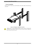
Страница 46: ...A Server AS 2114GT DNR User s Manual 46 Figure 3 7 Riser F Expansion Card Figure 3 8 Riser B Expansion Card...

Страница 47: ...47 Chapter 3 Maintenance and Component Installation Figure 3 9 Riser FR Expansion Card...

Страница 48: ...ied a Supermicro service technician Always ensure that new heatsinks are used Qualified heatsinks include thermal interface material TIM with specified dimension and thickness 1 Prior to assembly ensu...

Страница 49: ...place any failed fan at your earliest convenience with the same type and model Note For system fan operation the following hardware is required GPU Baseboard module PCIe transition board fan board mot...

Страница 50: ...failed fan at your earliest convenience with the same type and model Note For system fan operation the following hardware is required GPU Baseboard module PCIe transition board fan board motherboard...

Страница 51: ...out of the airflow path or use shorter cables The control panel LEDs display system heat status See Control Panel in Chapter 1 for details Overheating There are several possible responses if the syste...

Страница 52: ...e installed 2 Gently place the air shroud over the CPU heatsinks with the front snap locations lining up with metal chassis middle crossbar Be careful that the air shroud legs at either end do not int...

Страница 53: ...53 Chapter 3 Maintenance and Component Installation Figure 3 13 All Air Shrouds Installed Whole air shroud set on the Motherboard The whole air shroud set on the motherboard looks like the below image...

Страница 54: ...h power or fully configured systems 180 240V service is required An amber light will be illuminated on the power supply when the power is off An illuminated green light indicates that the power supply...

Страница 55: ...cations formerly known as NGFF These M 2 slots supports M Key PCIe 4 0 storage cards with form factors of 2242 2260 2280 and 22110 TPM Header Port 80 Connector TPM Port The JTPM2 header is used to con...

Страница 56: ...X B9 USB3_TP Onboard USB 13 2 0 Pin Definitions Pin Definition Pin Definition 1 5V 6 USB_P 2 5V 7 Ground 3 USB_N 8 Ground 4 USB_N 9 Key 5 USB_P 10 NC SlimSAS Ports The H12SSG AN6 has 11 PCIe 4 0 SlimS...

Страница 57: ...PWR2 JPWR3 and JPWR4 are all 8 pin 12V DC power inputs for GPUs that have been installed in the system s PCIe slots Refer to the table below for pin definitions GPU 12V 8 pin Power Pin Definitions Pin...

Страница 58: ...OM Port 3 USB Ports USB3 1 2 IPMI LAN Port 4 VGA Port 1 4 3 2 3 COM Port One serial communications COM port is included on the rear I O panel Universal Serial Bus USB Ports There are two USB 3 1 ports...

Страница 59: ...ch both rear and front UID LED indicators will turn on Press the UID switch again to turn off the LED indicators The UID Indicator provides easy identification of a system that may be in need of servi...

Страница 60: ...ins Connector Pins Jumper Setting 3 2 1 3 2 1 Clear CMOS JBT1 JBT1 is used to clear CMOS which will also clear any passwords Instead of pins this jumper consists of contact pads to prevent accidentall...

Страница 61: ...g to reset the system if an application hangs Jumping pins 2 3 will generate a non maskable interrupt signal for the application that hangs Watch Dog must also be enabled in BIOS The default setting i...

Страница 62: ...en Blinking BMC Normal Green Fast Blinking BMC Initializing UID LED Indicator LED1 The rear LED1 is located next to the UID switch The front UID LED is located on the front panel When you press the UI...

Страница 63: ...ing components Onboard Power LED Indicator LED Color Definition Off System Off power cable not connected Green System On M 2 Active LEDs LED4 and LED5 The M 2 Interface Detection LEDs indicate that an...

Страница 64: ...stallation ISO file That might be a DVD perhaps using an external USB SATA DVD drive or a USB flash drive or the IPMI KVM console 2 Go to the Supermicro web page for your motherboard and click on Down...

Страница 65: ...he bottom left corner Figure 5 2 Load Driver Link To load the driver browse the USB flash drive for the proper driver files Choose the SATA sSATA AHCI driver indicated then choose the storage drive on...

Страница 66: ...eferred Another option is to go to the Supermicro website at http www supermicro com products Find the product page for your motherboard and Download the Latest Drivers and Utilities Insert the flash...

Страница 67: ...email or Simple Network Management Protocol SNMP SuperDoctor 5 comes in local and remote management versions and can be used with Nagios to maximize your system monitoring needs With SuperDoctor 5 Ma...

Страница 68: ...m modules There are several BIOS settings that are related to IPMI For general documentation and information on IPMI visit our website at http www supermicro com products nfo IPMI cfm BMC ADMIN User P...

Страница 69: ...F2 etc Each main BIOS menu option is described in this manual The Main BIOS screen has two main frames The left frame displays all the options that can be configured Grayed out options cannot be confi...

Страница 70: ...e System Time Use this option to change the system date and time Highlight System Date or System Time using the arrow keys Enter new values using the keyboard Press the Tab key or the arrow keys to mo...

Страница 71: ...displays the CPLD version of the BIOS ROM used in the system Memory Information Total Memory This item displays the total size of memory available in the system Total Memory This feature displays the...

Страница 72: ...ss the submenu items Boot Feature Quiet Boot Use this feature to select the screen display between the POST messages and the OEM logo upon bootup Select Disabled to display the POST messages Select En...

Страница 73: ...ly reboot the system from a specified boot device after its initial boot failure The options are Disabled Legacy Boot and EFI Boot Power Configuration Watch Dog Function If enabled the Watch Dog Timer...

Страница 74: ...ocessor PSP firmware versions PSP Directory Level 1 Fixed PSP Recovery BL Ver SUM FW Version ABL Version PSP Directory Level 2 Updateable PSP Bootloader Version SUM FW Version ABL Version ACPI Setting...

Страница 75: ...ons are Auto IO 3F8h IRQ 4 IO 3F8h IRQ 3 4 5 6 7 9 10 11 12 IO 2F8h IRQ 3 4 5 6 7 9 10 11 12 IO 3E8h IRQ 3 4 5 6 7 9 10 11 12 and IO 2E8h IRQ 3 4 5 6 7 9 10 11 12 SOL Configuration Serial Port Select...

Страница 76: ...sure that the same speed is used in the host computer and the client computer A lower transmission speed may be required for long and busy lines The options are 9600 19200 38400 57600 and 115200 bits...

Страница 77: ...ber of rows and columns supported by legacy OS redirection to 80x24 or 80x25 Putty KeyPad This feature selects the settings for Function Keys and KeyPad used for Putty which is a terminal emulator des...

Страница 78: ...1 s in data bits is odd Select None if you do not want to send a parity bit with your data bits in transmission Select Mark to add a mark as a parity bit to be sent along with the data bits Select Spa...

Страница 79: ...following items will become available for user s configuration Console Redirection Settings Out of Band Mgmt Port The feature selects a serial port in a client server to be used by the Microsoft Windo...

Страница 80: ...d Global C state Control This setting is used to configure for Global C state Control Options include Disabled Enabled and Auto Local APIC Mode Options include Compatibility xAPIC x2APIC and Auto CCD...

Страница 81: ...nal purposes They will display some details about the detected CPUs on the motherboard such as CPU Version Number of Cores Running Processor Family Processor Model Microcode Patch Level L1 Instruction...

Страница 82: ...rleaving Note that the channel die and socket have requirements on memory populations and it will be ignored if the memory doesn t support the selected option Options include Disabled and Auto Memory...

Страница 83: ...lity to be decoded in above 4G address space only if the system supports 64 bit PCI decoding SR IOV Support If the system has SR IOV capable PCI E devices this setting will Enable or Disable the Singl...

Страница 84: ...Native Support and Vendor Defined Firmware JM2_A1 OPROM Use this setting to enable or disable the JM2_A1 OPROM option The options are Disabled and EFI JM2_B1 OPROM Use this setting to enable or disabl...

Страница 85: ...ting allows you to Enable or Disable IPv6 PXE boot support If disabled IPv6 PXE boot support will not be available IPv6 HTTP Support This setting allows you to Enable or Disable IPv6 HTTP boot support...

Страница 86: ...disable or enable OnChip SATA controller Options are Disabled Enabled and Auto SATA Hotplug Use this setting to disable or enable OnChip SATA Hotplug function Options are Disabled and Enabled SATA In...

Страница 87: ...the HTTP boot policy to Appply to all LANs Apply to each LAN and Boot Priority 1 instantly Priority of HTTP Boot Instance of Priority 1 Default to 1 Select IPv4 of IPv6 Choose to set the targeted LAN...

Страница 88: ...entered into the system configure the proper settings for the following items Add an Attempt Delete Attempts Change Attempt Order Intel I350 Gigabit Network Connection Port Configuration Menu Blink L...

Страница 89: ...certification GUID Commit Changes and Exit Use this feature to save all changes and exit TLS settings Discard Changes and Exit Use this feature to discard all changes and exit TLS settings Delete Cer...

Страница 90: ...atform Management Interface IPMI settings BMC Firmware Revision This item indicates the IPMI firmware revision used in your system IPMI Status This item indicates the status of the IPMI firmware insta...

Страница 91: ...fter each system reboot The options are No Yes On next reset and Yes On every reset When SEL is Full This feature allows the user to decide what the BIOS should do when the system event log is full Se...

Страница 92: ...the network that is attached to and request the next available IP address for this computer The options are DHCP and Static If the item above is set to Static the following items will become available...

Страница 93: ...BIOS Event settings Enabling Disabling Options SMBIOS Event Log Select Enabled to enable SMBIOS System Management BIOS Event Logging during system boot The options are Disabled and Enabled Erasing Set...

Страница 94: ...abled MECI Multiple Event Count Increment Enter the increment value for the multiple event counter Enter a number between 1 to 255 The default setting is 1 METW Multiple Event Count Time Window This i...

Страница 95: ...ministrator Password is erased the User Password will be cleared as well User Password Press Enter to create a new or change an existing User password Administrator Password Press Enter to set the adm...

Страница 96: ...CSM function is disabled Options include Enabled and Disabled Secure Boot Mode Use this item to select the secure boot mode The options are Standard and Custom CSM Support Select Enabled to support th...

Страница 97: ...lect Yes to load the new platform keys PK from the manufacturer s defaults Select No to load the platform keys from a file The options are Yes and No Provision Factory Default Keys Select Enabled to i...

Страница 98: ...uploads and installs an OSRecovery Signature You may select options for Set New for a factory default key or select Append to get it from a file The file formats accepted are 1 Public Key Certificate...

Страница 99: ...is option Enables or Disables the system to boot to an EFI OS after the boot failed from the legacy boot order FIXED BOOT ORDER Priorities This option prioritizes the order of bootable devices that th...

Страница 100: ...evice UEFI Hard Disk Drive BBS Priorities This feature allows the user to specify which UEFI devices are boot devices Boot Option 1 UEFI Network Drive BBS Priorities This feature specifies the boot de...

Страница 101: ...ot the computer Select Discard Changes and Exit from the Exit menu and press Enter Save Changes and Reset Select this option to reset the system after saving the changes Save Changes After completing...

Страница 102: ...bles the user to save any changes to the BIOS setup for future use Restore User Defaults To set this feature select Restore User Defaults from the Exit menu and press Enter Use this feature to retriev...

Страница 103: ...r assistance Only certified technicians should attempt to install or configure components Read this appendix in its entirety before installing or configuring components in the Supermicro chassis These...

Страница 104: ...po considere los riesgos de la corriente el ctrica y familiar cese con los procedimientos est ndar de prevenci n de accidentes Al final de cada advertencia encontrar el n mero que le ayudar a encontra...

Страница 105: ...en dient u zich bewust te zijn van de bij een elektrische installatie betrokken risico s en dient u op de hoogte te zijn van de standaard procedures om ongelukken te voorkomen Gebruik de nummers aan h...

Страница 106: ...mentaci n Attention Avant de brancher le syst me sur la source d alimentation consulter les directives d installation Circuit Breaker Waarschuwing Raadpleeg de installatie instructies voordat u het sy...

Страница 107: ...es del edificio Aseg rese de que el dispositivo de protecci n no sea superior a 250 V 20 A Attention Pour ce qui est de la protection contre les courts circuits surtension ce produit d pend de l insta...

Страница 108: ...e energ a y del cable el ctrico quitado de los m dulos de fuente de alimentaci n antes de tener acceso el interior del chasis para instalar o para quitar componentes de sistema Attention Le syst me do...

Страница 109: ...bels aangesloten op de voeding en van de behuizing te verwijderen Equipment Installation Warning Only trained and qualified personnel should be allowed to install replace or service this equipment War...

Страница 110: ...tention Il est vivement recommand de confier l installation le remplacement et la maintenance de ces quipements des personnels qualifi s et exp riment s Warning This unit is intended for installation...

Страница 111: ...a una de estas reas mediante la utilizaci n de una herramienta especial cerradura con llave u otro medio de seguridad Attention Cet appareil doit tre install e dans des zones d acc s r serv s L acc s...

Страница 112: ...emblable ou quivalent recommand e par le fabricant Jeter les piles usag es conform ment aux instructions du fabricant Advertencia Existe peligro de explosi n si la bater a se reemplaza de manera incor...

Страница 113: ...aanbevolen wordt Gebruikte batterijen dienen overeenkomstig fabrieksvoorschriften afgevoerd te worden Redundant Power Supplies Warning This unit might have more than one power supply connection All co...

Страница 114: ...omloos te maken Advertencia Puede que esta unidad tenga m s de una conexi n para fuentes de alimentaci n Para cortar por completo el suministro de energ a deben desconectarse todas las conexiones Atte...

Страница 115: ...vertencia Cuando el sistema est en funcionamiento el voltaje del plano trasero es peligroso Tenga cuidado cuando lo revise Attention Lorsque le syst me est en fonctionnement des tensions lectriques ci...

Страница 116: ...cumplir con las normas de electricidad locales y nacionales Backplane Waarschuwing Een gevaarlijke spanning of energie is aanwezig op de backplane wanneer het systeem in gebruik is Voorzichtigheid is...

Страница 117: ...le elektriciteitsvoorschriften Warnung Die Entsorgung dieses Produkts sollte gem allen Bestimmungen und Gesetzen des Landes erfolgen Warning Ultimate disposal of this product should be handled accordi...

Страница 118: ...recyclage de ce produit sont g n ralement soumis des lois et ou directives de respect de l environnement Renseignez vous aupr s de l organisme comp tent Hot Swap Fan Warning Warning Hazardous moving...

Страница 119: ...stornilladores y todos los objetos lejos de las aberturas del ventilador Attention Pieces mobiles dangereuses Se tenir a l ecart des lames du ventilateur Il est possible que les ventilateurs soient to...

Страница 120: ...UL oder CAS zertifizierten Kabeln mit UL CSA gekennzeichnet an Ger ten oder Produkten die nicht mit Supermicro gekennzeichnet sind AC AC UL CSA UL CSA Supermicro Supermicro UL CSA UL CSA Supermicro U...

Страница 121: ...le code pour tous les autres appareils lectriques sauf les produits d sign s par Supermicro seulement AC AC UL CSA UL CSA Supermicro UL CSA UL CSA Supermicro Advertencia Cuando instale el producto ut...

Страница 122: ...Aansluitmethode deze moet altijd voldoen aan de lokale voorschriften en veiligheidsnormen inclusief de juiste kabeldikte en stekker Het gebruik van niet geschikte Kabels en of Adapters kan een storin...

Страница 123: ...rt per node Three double width or six single width GPUs Drive Bays per node Four 2 5 hot swap hard drive carriers for NVMe drives PCI Expansion Slots per node One PCIe 4 0 x16 FHHL slot One PCIe 4 0 x...

Страница 124: ...N 61000 4 6 BS EN 61000 4 8 BS EN 61000 4 11 BS EN 55024 KN 32 KN 35 CNS 13438 CNS 14336 1 Product Safety 2014 35 EU LVD Directive UL CSA 62368 1 USA and Canada Electrical Equipment Safety Regulations...

Страница 125: ...0 01 wt Note 1 Exceeding 0 1 wt and exceeding 0 01 wt indicate that the percentage content of the restricted substance exceeds the reference percentage value of presence condition Note 2 indicates th...

Страница 126: ...126 A Server AS 2114GT DNR User s Manual PWS 2K63A 1R 200 240V 60 50Hz 15 12 5A x2 PWS 2K05A 1R 100 127V 60 50Hz 12 9 5A x2 200 240V 60 50Hz 10 9 8A x2 150 3...

Отзывы: