background image

1-16

X7SPA-L/X7SPA-H/X7SPA-HF/X7SPE-H/X7SPE-HF


User’s Manual

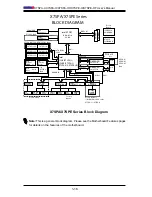
X7SPA/X7SPE Series Block Diagram

Note: 

This is a general block diagram. Please see the Motherboard Features pages 

for details on the features of the motherboard.

*SC/DC

Intel ATOM

SO

D

IM

M

 1

SO

D

IM

M

 2

DDR2 667

VGA

LVDS

Connector

Connector

Intel

ICH9 (X7SPA-L)

ICH9R (X7SPA-H,

X7SPA-HF, X7SPE-HF))

DMI

Intel 82574L

GbE(LAN2)

Intel 82574L

GbE(LAN1)

PCI-E x1

PCI-E x1

PCI-E x4

PCI-E x16

Slot

RJ45

RJ45

MDI

MDI

RMII

X7SPA/X7SPE Series

LPC

SATA GEN2

*x4/x6

USB 2.0 x10

WPCM450

BMC**

HD AUDIO

128MB

DDR2

PCI 33

USB x2

SDRAM

W83627DHG

SIO

IT8760E

LPC I/O

KB/MS

CONN

COM 1

CONN

COM 2

Header

COM 3

Header

COM 4

Header

ALC888

CODEC

FP

Header

SATA Port 4

*D410/D510

SATA Port 2

SATA Port 1

SATA Port 3

SATA Port 5

SATA Port 6

USB

Vertical

CONN x1

USB

Headerx3

(5Ports)

USB

Rear

CONN

*x4/x2

BLOCK DIAGRAM

PRT

PORT

12V DC PSU

4-PIN CONN

SLB9635TT_1.2

TPM

FROM BMC

ATX PSU

24PIN CONN

X7SPA-HF Only

**No BMC Installed on the 

X7SPA-L or X7SPA-H

X7SPA-H/X7SPA-HF/X7SPE-HF Only

X7SPA-H/

X7SPA-HF/

X7SPE-HF

Only

X7SPA-L Only

X7SPA-L Only

Factory

Option

Factory

Option

*x4 

X7SPA-L 

Only

Содержание X7SPA-H

Страница 1: ... X7SPA L USER S MANUAL Revision 1 1b X7SPA H X7SPA HF X7SPE HF X7SPE H ...

Страница 2: ...ALLING OR RECOVERING SUCH HARDWARE SOFTWARE OR DATA Any disputes arising between manufacturer and customer shall be governed by the laws of Santa Clara County in the State of California USA The State of California County of Santa Clara shall be the exclusive venue for the resolution of any such disputes Supermicro s total liability for all claims will not exceed the price paid for the hardware pro...

Страница 3: ...H X7SPE HF delivers cost effective performance in a small form factor This product is intended to be professionally installed and serviced by a techni cian Manual Organization Chapter 1 describes the features specifications and performance of the mainboard and provides detailed information about the chipset Chapter 2 provides hardware installation instructions Read this chapter when in stalling th...

Страница 4: ...yourself Danger Caution Instructions to be strictly followed to prevent catastrophic system failure or to avoid bodily injury Warning Critical information to prevent damage to the components or data loss Important Important information given to ensure proper system installa tion or to relay safety precautions Note Additional Information given to differentiate various models or pro vides informatio...

Страница 5: ...r Micro Computer B V Het Sterrenbeeld 28 5215 ML s Hertogenbosch The Netherlands Tel 31 0 73 6400390 Fax 31 0 73 6416525 Email sales supermicro nl General Information support supermicro nl Technical Support rma supermicro nl Customer Support Asia Pacific Address Super Micro Computer Inc 4F No 232 1 Liancheng Rd Chung Ho 235 Taipei County Taiwan R O C Tel 886 2 8226 3990 Fax 886 2 8226 3991 Web Sit...

Страница 6: ...SPE H X7SPE HF Quick Reference 1 10 Motherboard Features 1 14 X7SPA X7SPE Series Block Diagram 1 16 1 2 Chipset Overview 1 17 I O Controller Hub ICH9R X7SPA H X7SPA HF X7SPE H X7SPE HF 1 17 I O Controller Hub ICH9 X7SPA L 1 17 1 3 PC Health Monitoring 1 18 Recovery from AC Power Loss 1 18 Onboard Voltage Monitoring 1 18 Fan Status Monitor with Software 1 18 CPU Overheat LED and Control 1 18 1 4 Po...

Страница 7: ...PS 2 Keyboard and PS 2 Mouse Ports 2 7 Universal Serial Bus USB 2 8 Serial Ports 2 9 VGA Connector 2 10 LAN Ports IPMI 2 11 Front Control Panel 2 12 JF1 Header Pins 2 12 Front Control Panel Pin Definitions 2 13 Power LED 2 13 HDD LED 2 13 NIC1 NIC2 LED Indicators 2 13 Overheat OH Fan Fail LED 2 14 Power Fail LED 2 14 Reset Button 2 15 Power Button 2 15 NMI Button 2 15 2 5 Connecting Cables 2 16 AT...

Страница 8: ...r LED Speaker 2 27 BMC X7SPA HF X7SPE HF Only 2 27 VGA Enable X7SPA HF X7SPE HF only 2 28 HDA AC97 Select 2 28 Power Force On Enable Disable 2 29 DCD P5V Select 2 29 2 7 Onboard Indicators 2 30 LAN Port LEDs 2 30 2 8 Serial ATA and HDD Connections 2 31 SATA Connectors 2 31 Chapter 3 Troubleshooting 3 1 Troubleshooting Procedures 3 1 Before Power On 3 1 No Power 3 1 No Video 3 1 Memory Errors 3 2 L...

Страница 9: ...vanced Setup Configurations 4 4 4 4 Security Settings 4 20 4 5 Boot Settings 4 22 4 6 Exit Options 4 23 Appendix A POST Error Beep Codes Recoverable POST Error Beep Codes A 1 Appendix B Software Installation Instructions B 1 Installing Drivers B 1 B 2 Configuring Supero Doctor III B 2 Table of Contents ...

Страница 10: ...Notes X7SPA L X7SPA H X7SPA HF X7SPE H X7SPE HF User s Manual ...

Страница 11: ...ou with the highest standards in quality and performance Please check that the following items have all been included with your motherboard If anything listed here is damaged or missing contact your retailer All the following items are included in the retail box only One 1 Supermicro Mainboard Two 2 SATA cables CBL 0044L One 1 I O shield MCP 260 00003 00 One 1 Supermicro CD containing drivers and ...

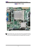
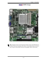
Страница 12: ...Manual X7SPA L Image Note All graphics shown in this manual were based upon the latest PCB Revision available at the time of publishing of the manual The motherboard you ve received may or may not look exactly the same as the graphics shown in this manual ...

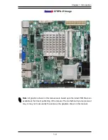
Страница 13: ...age Note All graphics shown in this manual were based upon the latest PCB Revision available at the time of publishing of the manual The motherboard you ve received may or may not look exactly the same as the graphics shown in this manual ...

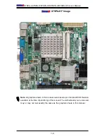
Страница 14: ...anual X7SPA HF Image Note All graphics shown in this manual were based upon the latest PCB Revision available at the time of publishing of the manual The motherboard you ve received may or may not look exactly the same as the graphics shown in this manual ...

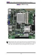
Страница 15: ...age Note All graphics shown in this manual were based upon the latest PCB Revision available at the time of publishing of the manual The motherboard you ve received may or may not look exactly the same as the graphics shown in this manual ...

Страница 16: ...anual X7SPE HF Image Note All graphics shown in this manual were based upon the latest PCB Revision available at the time of publishing of the manual The motherboard you ve received may or may not look exactly the same as the graphics shown in this manual ...

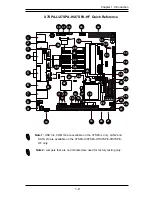
Страница 17: ... 1 2 ENABLE JPB BMC ENABLE DISABLE CD in JPT1 TPM ENABLE DISABLE 1 2 ENABLE 2 3 DISABLE AUDIO FP T SGPIO2 T SGPIO1 JPI2C PWR I2C JSMB1 SMBus1 JPUSB1 USB WAKE UP 2 3 DISABLE 1 2 ENABLE JWF1 DOM PWR JD1 1 3 PWR LED 4 7 SPEAKER ON ENABLE JI2C2 OFF DISABLE JI2C1 OFF DISABLE ON ENABLE JL2 AUDIO FRONT PANEL SELECT ON AC 97 FRONT PANEL OFF HD AUDIO FRONT PANEL JPG1 VGA 2 3 DISABLE 1 2 ENABLE 2 3 DISABLE ...

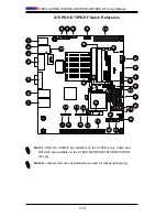
Страница 18: ...M2 JPI2C1 JWF1 J8 JVGA1 JPB FAN FAN COMS CLEAR 2 3 DISABLE 1 2 ENABLE JPB BMC ENABLE DISABLE JPT1 TPM ENABLE DISABLE 1 2 ENABLE 2 3 DISABLE T SGPIO2 T SGPIO1 JPI2C PWR I2C JSMB1 SMBus1 JPUSB1 USB WAKE UP 2 3 DISABLE 1 2 ENABLE JWF1 DOM PWR JD1 1 3 PWR LED 4 7 SPEAKER ON ENABLE JI2C2 OFF DISABLE JL2 AUDIO FRONT PANEL SELECT ON AC 97 FRONT PANEL OFF HD AUDIO FRONT PANEL JPG1 VGA 2 3 DISABLE 1 2 ENAB...

Страница 19: ...NT PANEL OFF HD AUDIO FRONT PANEL JPG1 VGA 2 3 DISABLE 1 2 ENABLE 2 3 DISABLE JPL2 1 2 ENABLE JPL1 1 2 ENABLE 2 3 DISABLE JL1 CHASISS INTRUSION JF1 PWR ON RST X OH FF NIC2 NIC1 HDD LED PWR LED X NMI 2 3 NMI JWD1 1 2 RST JBT1 LAN2 LAN1 I SATA5 I SATA2 I SATA4 I SATA1 I SATA3 I SATA0 SLOT1 PCI E X4 IN X16 SLOT SYS CPU KB MOUSE COM4 COM3 COM2 COM1 SODIMM2 SODIMM1 CPU REV 1 00 X7SPA L J6 J5 J10 J11 J1...

Страница 20: ...BLE JL2 AUDIO FRONT PANEL SELECT ON AC 97 FRONT PANEL OFF HD AUDIO FRONT PANEL JPG1 VGA 2 3 DISABLE 1 2 ENABLE 2 3 DISABLE JPL2 1 2 ENABLE JPL1 1 2 ENABLE 2 3 DISABLE JL1 CHASISS INTRUSION JF1 PWR ON RST X OH FF NIC2 NIC1 HDD LED PWR LED X NMI 2 3 NMI JWD1 1 2 RST JBT1 LAN2 LAN1 I SATA5 I SATA2 I SATA4 I SATA1 I SATA3 I SATA0 SYS CPU KB MOUSE COM2 COM1 SODIMM2 SODIMM1 CPU JPF 5 4 3 11 7 6 1 2 12 1...

Страница 21: ...8 Power Connector for Add on devices Note Do NOT plug the power supply into this socket 27 SATA 0 1 2 3 4 5 SATA Connectors SATA 2 3 is not available on the X7SPA L 29 JWF1 SATA Disk on Module DOM Power 30 T SGPIO 0 1 Serial General Purpose IO headers for SATA 31 JF1 FP Control Panel Header 32 JD1 External Buzzer Speaker Power LED Pins 1 3 Power LED Pins 4 7 External Speaker 33 JPI2C PWR supply I2...

Страница 22: ...y Pins 1 2 Enabled Pins 2 3 Disabled 24 JPUSB1 USB Wake up Enable Pins 1 2 Enabled 28 JWD1 Watch Dog Timer Pins 1 2 Reset 42 JPT1 Trusted Platform Module Enable Pins 1 2 Enabled Pins 2 3 Disabled 43 JPC3 COM3 Selection OEM option for the X7SPA H X7SPA HF X7SPE HF only Pins 1 2 RS232 Pins 2 3 TTL 44 JBT1 CMOS Clear See Chapter 2 46 J12 J13 Pin 1 DCD P5V Select COM3 COM4 OEM option for the X7SPA H X...

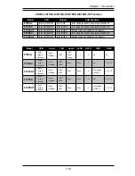
Страница 23: ... LAN1 LAN2 None None 6 No 0 1 5 10 X7SPE HF 2 rear 1 type A 5 header 1 rear 1 header LAN1 LAN2 None None 6 Yes shared on LAN1 0 1 5 10 X7SPA L X7SPA H X7SPA HF X7SPE H X7SPE HF Features Model CPU Chipset VGA Graphics X7SPA L Intel ATOM D410 Intel ICH9 Intel Graphics Media Accelerator GMA3150 X7SPA H Intel ATOM D510 Intel ICH9R Intel Graphics Media Accelerator GMA3150 X7SPA HF Intel ATOM D510 Intel...

Страница 24: ...200eW Graphics Accelerator X7SPA HF X7SPE HF only Expansion Slots One 1 PCI E 1 1 x4 Gen1 in x16 physical slot BIOS 32 Mb AMI BIOS SPI Flash BIOS PC Health Monitoring Onboard voltage monitors for CPU Cores Chipset Voltage Memory Voltage 1 8V 3 3V 5V 12V 3 3V standby 5V standby VBat HT Tachometer monitoring Status monitor for speed control on off control Supports 3 pin fans w o speed control Low no...

Страница 25: ...assis X7SPA H X7SPE H Only 6 SATA connectors for 6 devices with support for RAID 0 RAID 1 RAID 10 and RAID 5 in the Windows OS environment Dual 10 100 1000 LAN Intel 82574L Two Fast UART 16550 compatible serial ports one back panel one header Eight 8 USB 2 0 ports headers USB1 2 USB5 10 Two ports on the back panel five USB headers for front panel access and one on board Type A USB port Optimized f...

Страница 26: ...MDI RMII X7SPA X7SPE Series LPC SATA GEN2 x4 x6 USB 2 0 x10 WPCM450 BMC HD AUDIO 128MB DDR2 PCI 33 USB x2 SDRAM W83627DHG SIO IT8760E LPC I O KB MS CONN COM 1 CONN COM 2 Header COM 3 Header COM 4 Header ALC888 CODEC FP Header SATA Port 4 D410 D510 SATA Port 2 SATA Port 1 SATA Port 3 SATA Port 5 SATA Port 6 USB Vertical CONN x1 USB Headerx3 5Ports USB Rear CONN x4 x2 BLOCK DIAGRAM PRT PORT 12V DC P...

Страница 27: ...In addition the ICH9R offers the Intel Matrix Storage Technology which provides various RAID options for data protection and rapid data access It also supports the next generation of client management through the use of PROActive technology in conjunction with Intel s next generation Gigabit Ethernet controller Intel ICH9R System Features The I O Controller Hub provides the I O subsystem with acce...

Страница 28: ...fault set ting is Last State Onboard Voltage Monitoring The onboard voltage monitor will scan the following voltages continuously CPU Cores Chipset Voltage Memory Voltage 1 8V 3 3V 3 3V standby 5V 12V and Vbat Once a voltage becomes unstable it will give a warning or send an error message to the screen The User can adjust the voltage thresholds to define the sensitivity of the voltage monitor by u...

Страница 29: ... the system will enter a SoftOff state The monitor will be suspended and the hard drive will spin down Pressing the power button again will cause the whole system to wake up During the SoftOff state the ATX power supply provides power to keep the required circuitry in the system alive In case the system malfunctions and you want to turn off the power just press and hold the power button for 4 seco...

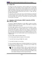
Страница 30: ...uvoton BMC interfaces with the host system via a PCI interface to commu nicate with the graphics core It supports USB 2 0 and 1 1 for remote keyboard mouse virtual media emulation It also provides LPC interface to control Super I O functions and is connected to the network via an external Ethernet PHY module It also communicates with onboard components via six SMBus interfaces fan control Platform...

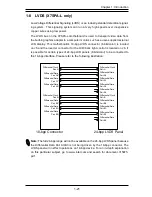
Страница 31: ...ease refer to the following illustration Differential Clock Pair A Differential Data Pair A0 Differential Data Pair A1 Differential Data Pair A2 18 bpp Connector Differential Clock Pair B Differential Data Pair B0 Differential Data Pair B1 Differential Data Pair B2 Differential Clock Pair A Differential Data Pair A0 Differential Data Pair A1 Differential Data Pair A2 Differential Clock Pair B Diff...

Страница 32: ...1 22 X7SPA L X7SPA H X7SPA HF X7SPE H X7SPE HF User s Manual Notes ...

Страница 33: ... its edges only do not touch its components peripheral chips memory modules or gold contacts When handling chips or modules avoid touching their pins Put the motherboard and peripherals back into their antistatic bags when not in use For grounding purposes make sure your computer chassis provides excellent conductivity between the power supply the case the mounting fasteners and the motherboard Us...

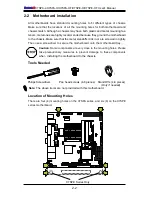
Страница 34: ...A3 I SATA0 SLOT1 PCI E X4 IN X16 SLOT SYS CPU KB MOUSE COM4 COM3 COM2 COM1 SODIMM2 SODIMM1 CPU REV 1 00 X7SPA L J6 J5 J10 J11 J12 J13 J14 JPF 2 2 Motherboard Installation All motherboards have standard mounting holes to fit different types of chassis Make sure that the locations of all the mounting holes for both motherboard and chassis match Although a chassis may have both plastic and metal moun...

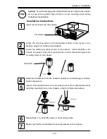
Страница 35: ...s Locate the matching mounting holes on the chassis Install standoffs in the chassis as needed Align the mounting holes on the motherboard against the mounting holes on the chassis Install the motherboard into the chassis carefully to avoid damage to mother board components Insert a Pan head 6 screw into a mounting hole on the motherboard and its matching mounting hole on the chassis using the Phi...

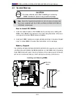
Страница 36: ...hen DIMM2 Pay attention to the notch along the bottom of the mod ule to prevent incorrect DIMM module installation Insert each DIMM module at an angle vertically and snap it into place Repeat 2 step 1 to install DIMM2 if needed See instructions on the next page Memory Support The X7SPA L X7SPA H X7SPA HF X7SPE H X7SPE HF supports up to 4GB of unbuffered Non ECC DDR2 SODIMMs 667MHz in 2 SO DIMM slo...

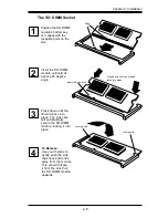
Страница 37: ...lease it from the slot Pull the SO DIMM module upwards The SO DIMM Socket Position the SO DIMM module s bottom key so it aligns with the receptive point on the slot Press down until the module locks into place The side clips will automatically secure the SO DIMM module locking it into place 1 2 3 4 Insert this end first Press down until the module locks into place Locking clip Locking clip Align ...

Страница 38: ...MB1 FAN1 FAN2 JCOM2 JCOM4 JPI2C1 JWF1 J8 JVGA1 CD1 JPB FAN FAN COMS CLEAR 2 3 DISABLE 1 2 ENABLE JPB BMC ENABLE DISABLE CD in JPT1 TPM ENABLE DISABLE 1 2 ENABLE 2 3 DISABLE AUDIO FP T SGPIO2 T SGPIO1 JPI2C PWR I2C JSMB1 SMBus1 JPUSB1 USB WAKE UP 2 3 DISABLE 1 2 ENABLE JWF1 DOM PWR JD1 1 3 PWR LED 4 7 SPEAKER ON ENABLE JI2C2 OFF DISABLE JI2C1 OFF DISABLE ON ENABLE JL2 AUDIO FRONT PANEL SELECT ON AC...

Страница 39: ...B5 JUSB4 JUSB3 JUSB2 JLPC80 R1050 JSMB1 FAN1 FAN2 JCOM2 JCOM4 JPI2C1 JWF1 J8 JVGA1 CD1 JPB FAN FAN COMS CLEAR 2 3 DISABLE 1 2 ENABLE JPB BMC ENABLE DISABLE CD in JPT1 TPM ENABLE DISABLE 1 2 ENABLE 2 3 DISABLE AUDIO FP T SGPIO2 T SGPIO1 JPI2C PWR I2C JSMB1 SMBus1 JPUSB1 USB WAKE UP 2 3 DISABLE 1 2 ENABLE JWF1 DOM PWR JD1 1 3 PWR LED 4 7 SPEAKER ON ENABLE JI2C2 OFF DISABLE JI2C1 OFF DISABLE ON ENABL...

Страница 40: ...Key 4 3 1 2 5 1 2 MH2 MH3 MH4 D17 JPW1 JUSB1 JD1 JPC3 JPUSB1 JWD1 JPG1 JBMC1 JPL1 JPT1 JPL2 JDIMM2 1 JDIMM1 JI2C2 JI2C1 JOH1 JL1 JL2 SP1 J2 J3 JBT1 JBAT1 JPCIE1 JUSB5 JUSB4 JUSB3 JUSB2 JLPC80 R1050 JSMB1 FAN1 FAN2 JCOM2 JCOM4 JPI2C1 JWF1 J8 JVGA1 CD1 JPB FAN FAN COMS CLEAR 2 3 DISABLE 1 2 ENABLE JPB BMC ENABLE DISABLE CD in JPT1 TPM ENABLE DISABLE 1 2 ENABLE 2 3 DISABLE AUDIO FP T SGPIO2 T SGPIO1 ...

Страница 41: ...3 JBT1 JBAT1 JPCIE1 JUSB5 JUSB4 JUSB3 JUSB2 JLPC80 R1050 JSMB1 FAN1 FAN2 JCOM2 JCOM4 JPI2C1 JWF1 J8 JVGA1 CD1 JPB FAN FAN COMS CLEAR 2 3 DISABLE 1 2 ENABLE JPB BMC ENABLE DISABLE CD in JPT1 TPM ENABLE DISABLE 1 2 ENABLE 2 3 DISABLE AUDIO FP T SGPIO2 T SGPIO1 JPI2C PWR I2C JSMB1 SMBus1 JPUSB1 USB WAKE UP 2 3 DISABLE 1 2 ENABLE JWF1 DOM PWR JD1 1 3 PWR LED 4 7 SPEAKER ON ENABLE JI2C2 OFF DISABLE JI2...

Страница 42: ...P 2 3 DISABLE 1 2 ENABLE JWF1 DOM PWR JD1 1 3 PWR LED 4 7 SPEAKER ON ENABLE JI2C2 OFF DISABLE JI2C1 OFF DISABLE ON ENABLE JL2 AUDIO FRONT PANEL SELECT ON AC 97 FRONT PANEL OFF HD AUDIO FRONT PANEL JPG1 VGA 2 3 DISABLE 1 2 ENABLE 2 3 DISABLE JPL2 1 2 ENABLE JPL1 1 2 ENABLE 2 3 DISABLE JL1 CHASISS INTRUSION JF1 PWR ON RST X OH FF NIC2 NIC1 HDD LED PWR LED X NMI 2 3 NMI JWD1 1 2 RST JBT1 LAN2 LAN1 I ...

Страница 43: ...MC ENABLE DISABLE CD in JPT1 TPM ENABLE DISABLE 1 2 ENABLE 2 3 DISABLE AUDIO FP T SGPIO2 T SGPIO1 JPI2C PWR I2C JSMB1 SMBus1 JPUSB1 USB WAKE UP 2 3 DISABLE 1 2 ENABLE JWF1 DOM PWR JD1 1 3 PWR LED 4 7 SPEAKER ON ENABLE JI2C2 OFF DISABLE JI2C1 OFF DISABLE ON ENABLE JL2 AUDIO FRONT PANEL SELECT ON AC 97 FRONT PANEL OFF HD AUDIO FRONT PANEL JPG1 VGA 2 3 DISABLE 1 2 ENABLE 2 3 DISABLE JPL2 1 2 ENABLE J...

Страница 44: ...2 1 2 ENABLE JPL1 1 2 ENABLE 2 3 DISABLE JL1 CHASISS INTRUSION JF1 PWR ON RST X OH FF NIC2 NIC1 HDD LED PWR LED X NMI 2 3 NMI JWD1 1 2 RST JBT1 LAN2 LAN1 I SATA5 I SATA2 I SATA4 I SATA1 I SATA3 I SATA0 SLOT1 PCI E X4 IN X16 SLOT SYS CPU KB MOUSE COM4 COM3 COM2 COM1 SODIMM2 SODIMM1 CPU REV 1 00 X7SPA L J6 J5 J10 J11 J12 J13 J14 JPF Front Control Panel JF1 contains header pins for various buttons an...

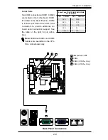
Страница 45: ...D1 1 2 RST JBT1 LAN2 LAN1 I SATA5 I SATA2 I SATA4 I SATA1 I SATA3 I SATA0 SLOT1 PCI E X4 IN X16 SLOT SYS CPU KB MOUSE COM4 COM3 COM2 COM1 SODIMM2 SODIMM1 CPU REV 1 00 X7SPA L J6 J5 J10 J11 J12 J13 J14 JPF Front Control Panel Pin Definitions Power LED The Power LED connection is located on pins 15 and 16 of JF1 Refer to the table on the right for pin definitions Power LED Pin Definitions JF1 Pin De...

Страница 46: ...IC2 NIC1 HDD LED PWR LED X NMI 2 3 NMI JWD1 1 2 RST JBT1 LAN2 LAN1 I SATA5 I SATA2 I SATA4 I SATA1 I SATA3 I SATA0 SLOT1 PCI E X4 IN X16 SLOT SYS CPU KB MOUSE COM4 COM3 COM2 COM1 SODIMM2 SODIMM1 CPU REV 1 00 X7SPA L J6 J5 J10 J11 J12 J13 J14 JPF Power Button OH Fan Fail LED 1 NIC1 LED Reset Button 2 HDD LED Power LED Vcc Vcc Vcc Vcc Ground Ground 19 20 Vcc X Ground NMI X Vcc NIC2 LED Power Fail LE...

Страница 47: ...SLOT SYS CPU KB MOUSE COM4 COM3 COM2 COM1 SODIMM2 SODIMM1 CPU REV 1 00 X7SPA L J6 J5 J10 J11 J12 J13 J14 JPF Power Button The Power Button connection is located on pins 1 and 2 of JF1 Momentarily contacting both pins will power on off the system To turn off the power when set to suspend mode press the button for at least 4 seconds Refer to the table on the right for pin definitions Power Button Pi...

Страница 48: ...CD in JPT1 TPM ENABLE DISABLE 1 2 ENABLE 2 3 DISABLE AUDIO FP T SGPIO2 T SGPIO1 JPI2C PWR I2C JSMB1 SMBus1 JPUSB1 USB WAKE UP 2 3 DISABLE 1 2 ENABLE JWF1 DOM PWR JD1 1 3 PWR LED 4 7 SPEAKER ON ENABLE JI2C2 OFF DISABLE JI2C1 OFF DISABLE ON ENABLE JL2 AUDIO FRONT PANEL SELECT ON AC 97 FRONT PANEL OFF HD AUDIO FRONT PANEL JPG1 VGA 2 3 DISABLE 1 2 ENABLE 2 3 DISABLE JPL2 1 2 ENABLE JPL1 1 2 ENABLE 2 3...

Страница 49: ... ON RST X OH FF NIC2 NIC1 HDD LED PWR LED X NMI 2 3 NMI JWD1 1 2 RST JBT1 LAN2 LAN1 I SATA5 I SATA2 I SATA4 I SATA1 I SATA3 I SATA0 SLOT1 PCI E X4 IN X16 SLOT SYS CPU KB MOUSE COM4 COM3 COM2 COM1 SODIMM2 SODIMM1 CPU REV 1 00 X7SPA L J6 J5 J10 J11 J12 J13 J14 JPF Fan Header Pin Definitions Pin Definition 1 Ground 2 12V 3 Tachometer 4 PWM_Control Fan Headers The X7SPA L X7SPA H X7SPA HF X7SPE H X7SP...

Страница 50: ... PWR I2C JSMB1 SMBus1 JPUSB1 USB WAKE UP 2 3 DISABLE 1 2 ENABLE JWF1 DOM PWR JD1 1 3 PWR LED 4 7 SPEAKER ON ENABLE JI2C2 OFF DISABLE JI2C1 OFF DISABLE ON ENABLE JL2 AUDIO FRONT PANEL SELECT ON AC 97 FRONT PANEL OFF HD AUDIO FRONT PANEL JPG1 VGA 2 3 DISABLE 1 2 ENABLE 2 3 DISABLE JPL2 1 2 ENABLE JPL1 1 2 ENABLE 2 3 DISABLE JL1 CHASISS INTRUSION JF1 PWR ON RST X OH FF NIC2 NIC1 HDD LED PWR LED X NMI...

Страница 51: ...X OH FF NIC2 NIC1 HDD LED PWR LED X NMI 2 3 NMI JWD1 1 2 RST JBT1 LAN2 LAN1 I SATA5 I SATA2 I SATA4 I SATA1 I SATA3 I SATA0 SLOT1 PCI E X4 IN X16 SLOT SYS CPU KB MOUSE COM4 COM3 COM2 COM1 SODIMM2 SODIMM1 CPU REV 1 00 X7SPA L J6 J5 J10 J11 J12 J13 J14 JPF Chassis Intrusion SATA DOM Power I2C Connector A Chassis Intrusion A Chassis Intrusion header is located at JL1 on the motherboard Attach the app...

Страница 52: ...NEL SELECT ON AC 97 FRONT PANEL OFF HD AUDIO FRONT PANEL JPG1 VGA 2 3 DISABLE 1 2 ENABLE 2 3 DISABLE JPL2 1 2 ENABLE JPL1 1 2 ENABLE 2 3 DISABLE JL1 CHASISS INTRUSION JF1 PWR ON RST X OH FF NIC2 NIC1 HDD LED PWR LED X NMI 2 3 NMI JWD1 1 2 RST JBT1 LAN2 LAN1 I SATA5 I SATA2 I SATA4 I SATA1 I SATA3 I SATA0 SLOT1 PCI E X4 IN X16 SLOT SYS CPU KB MOUSE COM4 COM3 COM2 COM1 SODIMM2 SODIMM1 CPU REV 1 00 X...

Страница 53: ...7 FRONT PANEL OFF HD AUDIO FRONT PANEL JPG1 VGA 2 3 DISABLE 1 2 ENABLE 2 3 DISABLE JPL2 1 2 ENABLE JPL1 1 2 ENABLE 2 3 DISABLE JL1 CHASISS INTRUSION JF1 PWR ON RST X OH FF NIC2 NIC1 HDD LED PWR LED X NMI 2 3 NMI JWD1 1 2 RST JBT1 LAN2 LAN1 I SATA5 I SATA2 I SATA4 I SATA1 I SATA3 I SATA0 SLOT1 PCI E X4 IN X16 SLOT SYS CPU KB MOUSE COM4 COM3 COM2 COM1 SODIMM2 SODIMM1 CPU REV 1 00 X7SPA L J6 J5 J10 J...

Страница 54: ...on of the motherboard jumpers can be used to choose between optional settings Jumpers create shorts between two pins to change the function of the connector Pin 1 is identified with a square solder pad on the printed circuit board Note On two pin jumpers Closed means the jumper is on and Open means the jumper is off the pins ...

Страница 55: ...BLE 1 2 ENABLE 2 3 DISABLE AUDIO FP T SGPIO2 T SGPIO1 JPI2C PWR I2C JSMB1 SMBus1 JPUSB1 USB WAKE UP 2 3 DISABLE 1 2 ENABLE JWF1 DOM PWR JD1 1 3 PWR LED 4 7 SPEAKER ON ENABLE JI2C2 OFF DISABLE JI2C1 OFF DISABLE ON ENABLE JL2 AUDIO FRONT PANEL SELECT ON AC 97 FRONT PANEL OFF HD AUDIO FRONT PANEL JPG1 VGA 2 3 DISABLE 1 2 ENABLE 2 3 DISABLE JPL2 1 2 ENABLE JPL1 1 2 ENABLE 2 3 DISABLE JL1 CHASISS INTRU...

Страница 56: ...SODIMM1 CPU REV 1 00 X7SPA L J6 J5 J10 J11 J12 J13 J14 JPF CMOS Clear JBT1 is used to clear CMOS Instead of pins this jumper consists of contact pads to prevent accidental clearing of CMOS To clear CMOS use a metal object such as a small screwdriver to touch both pads at the same time to short the connection Always remove the AC power cord from the system before clear ing CMOS Important For an ATX...

Страница 57: ...ISS INTRUSION JF1 PWR ON RST X OH FF NIC2 NIC1 HDD LED PWR LED X NMI 2 3 NMI JWD1 1 2 RST JBT1 LAN2 LAN1 I SATA5 I SATA2 I SATA4 I SATA1 I SATA3 I SATA0 SLOT1 PCI E X4 IN X16 SLOT SYS CPU KB MOUSE COM4 COM3 COM2 COM1 SODIMM2 SODIMM1 CPU REV 1 00 X7SPA L J6 J5 J10 J11 J12 J13 J14 JPF A USB Wake up A USB Wake Up Use JPUSB jumper to enable the function of System Waking Up via USB devices This jumper ...

Страница 58: ...nition Pins 1 2 RS232 default Pins 2 3 TTL Open Disabled MH2 MH3 MH4 D17 JPW1 JUSB1 JD1 JPC3 JPUSB1 JWD1 JPG1 JBMC1 JPL1 JPT1 JPL2 JDIMM2 1 JDIMM1 JI2C2 JI2C1 JOH1 JL1 JL2 SP1 J2 J3 JBT1 JBAT1 JPCIE1 JUSB5 JUSB4 JUSB3 JUSB2 JLPC80 R1050 JSMB1 FAN1 FAN2 JCOM2 JCOM4 JPI2C1 JWF1 J8 JVGA1 CD1 JPB FAN FAN COMS CLEAR 2 3 DISABLE 1 2 ENABLE JPB BMC ENABLE DISABLE CD in JPT1 TPM ENABLE DISABLE 1 2 ENABLE ...

Страница 59: ... JD1 JPC3 JPUSB1 JWD1 JPG1 JBMC1 JPL1 JPT1 JPL2 JDIMM2 1 JDIMM1 JI2C2 JI2C1 JOH1 JL1 JL2 SP1 J2 J3 JBT1 JBAT1 JPCIE1 JUSB5 JUSB4 JUSB3 JUSB2 JLPC80 R1050 JSMB1 FAN1 FAN2 JCOM2 JCOM4 JPI2C1 JWF1 J8 JVGA1 CD1 JPB FAN FAN COMS CLEAR 2 3 DISABLE 1 2 ENABLE JPB BMC ENABLE DISABLE CD in JPT1 TPM ENABLE DISABLE 1 2 ENABLE 2 3 DISABLE AUDIO FP T SGPIO2 T SGPIO1 JPI2C PWR I2C JSMB1 SMBus1 JPUSB1 USB WAKE U...

Страница 60: ... JLPC80 R1050 JSMB1 FAN1 FAN2 JCOM2 JCOM4 JPI2C1 JWF1 J8 JVGA1 CD1 JPB FAN FAN COMS CLEAR 2 3 DISABLE 1 2 ENABLE JPB BMC ENABLE DISABLE CD in JPT1 TPM ENABLE DISABLE 1 2 ENABLE 2 3 DISABLE AUDIO FP T SGPIO2 T SGPIO1 JPI2C PWR I2C JSMB1 SMBus1 JPUSB1 USB WAKE UP 2 3 DISABLE 1 2 ENABLE JWF1 DOM PWR JD1 1 3 PWR LED 4 7 SPEAKER ON ENABLE JI2C2 OFF DISABLE JI2C1 OFF DISABLE ON ENABLE JL2 AUDIO FRONT PA...

Страница 61: ...2 3 DISABLE 1 2 ENABLE 2 3 DISABLE JPL2 1 2 ENABLE JPL1 1 2 ENABLE 2 3 DISABLE JL1 CHASISS INTRUSION JF1 PWR ON RST X OH FF NIC2 NIC1 HDD LED PWR LED X NMI 2 3 NMI JWD1 1 2 RST JBT1 LAN2 LAN1 I SATA5 I SATA2 I SATA4 I SATA1 I SATA3 I SATA0 SLOT1 PCI E X4 IN X16 SLOT SYS CPU KB MOUSE COM4 COM3 COM2 COM1 SODIMM2 SODIMM1 CPU REV 1 00 X7SPA L J6 J5 J10 J11 J12 J13 J14 JPF A B A Power Force On DCD P5V ...

Страница 62: ...OMS CLEAR 2 3 DISABLE 1 2 ENABLE JPB BMC ENABLE DISABLE CD in JPT1 TPM ENABLE DISABLE 1 2 ENABLE 2 3 DISABLE AUDIO FP T SGPIO2 T SGPIO1 JPI2C PWR I2C JSMB1 SMBus1 JPUSB1 USB WAKE UP 2 3 DISABLE 1 2 ENABLE JWF1 DOM PWR JD1 1 3 PWR LED 4 7 SPEAKER ON ENABLE JI2C2 OFF DISABLE JI2C1 OFF DISABLE ON ENABLE JL2 AUDIO FRONT PANEL SELECT ON AC 97 FRONT PANEL OFF HD AUDIO FRONT PANEL JPG1 VGA 2 3 DISABLE 1 ...

Страница 63: ...A2 I SATA4 I SATA1 I SATA3 I SATA0 SLOT1 PCI E X4 IN X16 SLOT SYS CPU KB MOUSE COM4 COM3 COM2 COM1 SODIMM2 SODIMM1 CPU REV 1 00 X7SPA L J6 J5 J10 J11 J12 J13 J14 JPF 2 8 Serial ATA and HDD Connections Note the following conditions when connecting the Serial ATA and hard disk drive cables Be sure to use the correct cable for each connector Refer to Page 1 1 for cables that came with your shipment A...

Страница 64: ...2 32 X7SPA L X7SPA H X7SPA HF X7SPE H X7SPE HF User s Manual Notes ...
Страница 65: ...d and chas sis 3 Disconnect all ribbon wire cables from the motherboard including those for the keyboard and mouse Also be sure to remove all add on cards 4 Connect the chassis speaker and the power LED to the motherboard Check all jumper settings as well No Power 1 Make sure that there are no short circuits between the motherboard and chas sis 2 Make sure that all jumpers are set to their default...

Страница 66: ... supply may cause the system to lose the CMOS setup information Refer to Section 1 5 for details on recommended power supplies 2 The battery on your motherboard may be old Check to verify that it still supplies 3VDC If it does not replace it with a new one 3 If the above steps do not fix the Setup Configuration problem contact your vendor for repairs 3 2 Technical Support Procedures Before contact...

Страница 67: ...of memory does my motherboard support Answer The X7SPA L X7SPA H X7SPA HF X7SPE H X7SPE HF supports up to 4GB of unbuffered Non ECC DDR2 667MHz two way interleaved or non interleaved SO DIMM SDRAM See Section 2 4 for details on installing memory Question Why does Microsoft Windows XP SP2 and Windows Vista show less memory than what is physically installed Answer Microsoft implemented a design chan...

Страница 68: ...h to flash the BIOS Then boot the system to the floppy disk The BIOS utility will automatically flash the BIOS without any prompts Please note that this process may take a few minutes to complete Do not be concerned if the screen is paused for a few minutes Warning Do not shut down or reset the system while updating the BIOS to prevent possible system boot failure When the BIOS flashing screen is ...

Страница 69: ... the manufacturer the RMA number should be prominently displayed on the outside of the shipping carton and mailed prepaid or hand carried Ship ping and handling charges will be applied for all orders that must be mailed when service is complete This warranty only covers normal consumer use and does not cover damages incurred in shipping or from failure due to the alteration misuse abuse or imprope...

Страница 70: ...3 6 X7SPA L X7SPA H X7SPA HF X7SPE H X7SPE HF User s Manual Notes ...
Страница 71: ...left frame displays all the options that can be configured Grayed out options cannot be configured Options in blue can be configured by the user The right frame displays the key legend Above the key legend is an area reserved for a text message When an option is selected in the left frame it is highlighted in white Often a text message will accompany it Note the AMI BIOS has default text messages ...

Страница 72: ... Do not upgrade the BIOS unless your system has a BIOS related issue Flashing the wrong BIOS can cause irreparable damage to the system In no event shall Supermicro be liable for direct indirect special incidental or consequential damages arising from a BIOS update If you have to update the BIOS do not shut down or reset the system while the BIOS is updating This is to avoid possible boot failure ...

Страница 73: ...move between fields The date must be entered in Day MM DD YY format The time is entered in HH MM SS format Note The time is in the 24 hour format For example 5 30 P M appears as 17 30 00 Supermicro X7SPA L X7SPA H X7SPA HF X7SPE H X7SPE HF Version Build Date Processor The AMI BIOS will automatically display the status of processor as shown below Type of Processor Speed Physical Count Logical Count...

Страница 74: ...educe the time needed for system boot The options are Enabled and Disabled Quiet Boot This option allows the bootup screen options to be modified between POST mes sages or the OEM logo Select Disabled to display the POST messages Select Enabled to display the OEM logo instead of the normal POST messages The op tions are Enabled and Disabled AddOn ROM Display Mode This sets the display mode for Opt...

Страница 75: ...ly or wait for 4 seconds when it is pressed The options are Instant Off and 4 Seconds Override Restore on AC Power Loss Use this feature to set the power state after a power outage Select Power Off for the system power to remain off after a power loss Select Power On for the system power to be turned on after a power loss Select Last State to allow the system to resume its last state before a powe...

Страница 76: ...ed to enhance system stability The options are Disabled and Enabled Max CPUID Value Limit This feature allows the user to set the maximum CPU ID value Enable this function to boot the legacy operating systems that cannot support processors with extended CPUID functions The options are Enabled and Disabled for the Windows OS Execute Disable Bit Capability Available when supported by the OS and the ...

Страница 77: ...ed is selected DRAM CAS Latency The options are 3 4 5 and 6 DRAM RAS to CAS Delay The options are 3 DRAM Clocks 4 DRAM Clocks 5 DRAM Clocks and 6 DRAM Clocks DRAM RAS Precharge The options are 3 DRAM Clocks 4 DRAM Clocks 5 DRAM Clocks and 6 DRAM Clocks DRAM RAS Activate to Precharge The options are 9 DRAM Clocks 10 DRAM Clocks 11 DRAM Clocks 12 DRAM Clocks 13 DRAM Clocks 14 DRAM Clocks and 15 DRAM...

Страница 78: ...ive State Power Management Select Enabled to start Active State Power Management for signal transactions between L0 and L1 Links on the PCI Express Bus This maximizes power saving and transaction speed The options are Enabled and Disabled Reserved Page Route This feature allows the user to decide which bus to send debug information to The options are Disabled PCI and LPC USB Functions This feature...

Страница 79: ...er to select the drive type for SATA 1 The options are IDE RAID and AHCI SATA 2 Configuration Available if IDE is enabled under Configure SATA 1 as above Selecting Enhanced will set SATA 2 to native SATA mode The options are Dis abled and Enhanced IDE Detect Timeout sec Use this feature to set the time out value for the BIOS to detect the ATA ATAPI devices installed in the system The options are 0...

Страница 80: ...rogrammable I O Mode programs timing cycles between the IDE drive and the programmable IDE controller As the PIO mode increases the cycle time decreases The options are Auto 0 1 2 3 and 4 Select Auto to allow the AMI BIOS to automatically detect the PIO mode Use this value if the IDE disk drive support cannot be determined Select 0 to allow the AMI BIOS to use PIO mode 0 It has a data transfer rat...

Страница 81: ...of 33 3 MBs Select UDMA3 to allow the BIOS to use Ultra DMA mode 3 It has a data transfer rate of 66 6 MBs Select UDMA4 to allow the BIOS to use Ultra DMA mode 4 It has a data transfer rate of 100 MBs The options are Auto SWDMAn MWDMAn and UDMAn S M A R T For Hard disk drives Self Monitoring Analysis and Reporting Technology SMART can help predict impending drive failures Select Auto to allow the ...

Страница 82: ...o enable or disable PCI slot Option ROMs The options are Dis abled and Enabled Load Onboard LAN 1 Option ROM Load Onboard LAN 2 Option ROM Select Enabled to load the onboard LAN Option ROM for the LAN port as specified The options are Enabled and Disabled Initiate Graphics Adapter Use this feature to select the graphics controller to be used as the primary boot device The options are Other Onboard...

Страница 83: ... control for Console Redirection The options are None Hardware and Software Redirection After BIOS POST Select Disabled to turn off Console Redirection after Power On Self Test POST Select Always to keep Console Redirection active all the time after POST Note This setting may not be supported by some operating systems Select Boot Loader to keep Console Redirection active during POST and Boot Loade...

Страница 84: ...at alarm including the LED and the buzzer to be triggered when the CPU temperature reaches about 5oC above the threshold temperature as predefined by the CPU manufacturer to give the CPU and system fans additional time needed for CPU and system cooling In both the alarms above please take immediate action as shown below CPU Temperature The CPU Temperature feature will display the CPU temperature s...

Страница 85: ...oblems Note the system may shut down if it con tinues for a long period to prevent damage to the CPU Notes The CPU thermal technology that reports absolute temperatures Celsius Fahrenheit has been upgraded to a more advanced feature by Intel in its newer processors The basic concept is that each CPU is embedded by a unique temperature information that the motherboard can read This Temperature Thre...

Страница 86: ...M Cycle for best power efficiency and maximum quietness The Options are Full Speed 100 of PWM Cycle Performance 70 of PWM Cycle Balanced 50 of PWM Cycle and Energy Saving 30 of PWM Cycle CPU Vcore AVCC 3 3Vcc 12V V_DIMM 5V 12V 3 3Vsb and Vbat This feature displays the voltage readings for the described components ACPI Configuration Use this feature to configure Advanced Configuration and Power Int...

Страница 87: ... and Disabled APIC ACPI SCI IRQ When this item is set to Enabled APIC ACPI SCI IRQ is supported by the system The options are Enabled and Disabled Headless Mode This feature is used to enable the system to function without a keyboard monitor or mouse attached The options are Enabled and Disabled ACPI Version Features The options are ACPI v1 0 ACPI v2 0 and ACPI v3 0 Please refer to ACPI s website ...

Страница 88: ...ber Enter the channel number for the SET LAN Config com mand This is initially set to 1 Press or on your keyboard to change the Channel Number Channel Number Status This feature returns the channel status for the Channel Number selected above Channel Number is OK or Wrong Channel Number IP Address Source This feature selects whether the IP address Subnet Mask and Gateway Address are automatically ...

Страница 89: ...eset System Power Down Power Cycle BMC WatchDog TimeOut Min Sec This option appears if BMC Watch Dog Timer Action above is enabled This is a timed delay in minutes or seconds before a system power down or reset after an operating system failure is detected The options are 5 Min 1 Min 30 Sec and 10 Sec Event Log Configuration View Event Log Use this option to view the System Event Log Mark all even...

Страница 90: ...user password has been entered for the system Clear means such a password has not been used and Set means a user password has been entered for the system Change Supervisor Password Select this feature and press Enter to access the submenu and then type in a new Supervisor Password User Access Level Available when Supervisor Password is set as above Available options are Full Access grants full Use...

Страница 91: ...ar User Password Available only if User Password has been set Password Check Available options are Setup and Always Boot Sector Virus Protection When Enabled the AMI BOIS displays a warning when any program or virus is sues a Disk Format command or attempts to write to the boot sector of the hard disk drive The options are Enabled and Disabled ...

Страница 92: ...ot device 4th boot device 5th boot device and Disabled 1st Boot Device 1st Floppy Drive 2nd Boot Device USB XXXXXXXXX 3rd Boot Device SATA XXXXXXXXX 4th Boot Device Network XXXXXXXXX Hard Disk Drives This feature allows the user to specify the sequence of priority from the available Hard Drives 1st Drive SATA XXXXXXXXXX 2nd Drive SATA XXXXXXXXXX 4 5 Boot Settings Use this feature to configure Boot...

Страница 93: ...Devices Select this option to retry booting from the configured boot devices if the systems fail to boot initially The options are Disabled and Enabled 4 6 Exit Options Select the Exit tab from the AMI BIOS Setup Utility screen to enter the Exit BIOS Setup screen Save Changes and Exit When you have completed the system configuration changes select this option to leave the BIOS Setup Utility and re...

Страница 94: ...d press Enter to discard all the changes and return to the AMI BIOS Utility Program Load Optimal Defaults To set this feature select Load Optimal Defaults from the Exit menu and press Enter Then select OK to allow the AMI BIOS to automatically load Optimal De faults to the BIOS Settings The Optimal settings are designed for maximum system performance but may not work best for all computer applicat...

Страница 95: ... Beep Codes for recoverable POST errors Recoverable POST Error Beep Codes When a recoverable type of error occurs during POST BIOS will display a POST code that describes the problem BIOS may also issue one of the following beep codes 1 long and two short beeps video configuration error 1 repetitive long beep no memory detected 1 continuous beep with the front panel Overheat LED on system overheat...

Страница 96: ...A 2 X7SPA L X7SPA H X7SPA HF X7SPE H X7SPE HF User s Manual Notes ...
Страница 97: ...g each item you must re boot the system before proceeding with the next item on the list The bottom icon with a CD on it allows you to view the entire contents of the CD Appendix B Software Installation Instructions B 1 Installing Drivers After you ve installed the Windows Operating System a screen as shown below will appear You are ready to install software programs and drivers that have not yet ...

Страница 98: ...ro Doctor III displays crucial system information such as CPU temperature system voltages and fan status See the Figure below for a display of the Supero Doctor III interface Note 1 Both default user name and password are ADMIN Note 2 In the Windows OS environment the Supero Doctor III settings take precedence over the BIOS settings When first installed Supero Doctor III adopts the temperature thr...

Страница 99: ...ote Control Note SD III Software Revision 1 0 can be downloaded from our Web site at ftp ftp supermicro com utility Supero_Doctor_III You can also download SDIII User s Guide at http www supermicro com PRODUCT Manuals SDIII UserGuide pdf For Linux we will still recommend that you use Supero Doctor II ...

Страница 100: ...B 4 X7SPA L X7SPA H X7SPA HF X7SPE H X7SPE HF User s Manual Notes ...
Страница 101: ...cted to result in significant injury or loss of life or catastrophic property damage Accordingly Supermicro disclaims any and all liability and should buyer use or sell such products for use in such ultra hazardous applications it does so entirely at its own risk Furthermore buyer agrees to fully indemnify defend and hold Supermicro harmless for and against any and all claims demands actions litig...

Отзывы: