MID POWER
4 x 37dBm Output
5G NR Compliant
© Sunwave CG_CF_M2 v2.1.0 | 25 of 47
Contact us today:
www.sunwave.com
[email protected]
Module Gain Adjustment (Attenuation)
In CrossFire, the downlink input power of the A2 is specified as 0dBm, and the maximum allowable input power is
15dBm. CrossFire has an automatic level control (ALC) function to maintain the input power around 0 at the A2 input
port. What’s more, the A2 and
M2 digital board have attenuation configuration for Gain Adjustment.
Gain Adjustment on A2 (Active Combiner)
1.
Open the Master A2 OMT.
2.
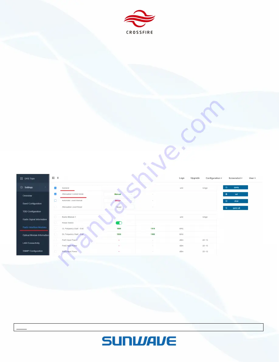
Go to
Settings -> Radio Interface Modules -> General
.
3.
Dropdown
Attenuation Control Mode
and select
Manual/Automatic
mode as designed.
Automatic Mode:
The internal ALC function is working when the peak input power exceeds 0 dBm.
Manual Mode:
Reduce the input power by setting the attenuation manually.
Adjust Interval:
The interval time to automatically reduce the attenuation in 2dB step when the peak input
power decrease in Automatic Mode.
Combiner Att Reset:
Reset all the attenuation values.
4.
Click the checkbox to select this parameter and click
Set
to validate it.
Figure 26.
Attenuation Control Mode
5.
Go to
Settings -> Radio Interface Modules -> Radio Module
6.
Locate the field and set the appropriate values:
Manual Mode:
Set the appropriate value in the field of
Port Attenuation Value
.
for example: if Port 1 input power is 5.5dBm / Port 2 input power is 9.0dBm and the composite output power is
divided by fifty-fifty, set 8.5 dB (5.5dB + 3dB) in Port 1 Attenuation Value and 12.5 dB (9.0dB +3dB) in Port 2
Attenuation Value.
Note:
Extra 3dB attenuation is used for power distribution.